 Guido
GuidoThe EBAZ4205 board
The best resources I found to understand how to manage the board are:
STEPS TO CHECK IF THE BOARD IS OK
After 1 month my board arrived from China.
As expected there's no 25MHz crystal for Ethernet but the board is hardware configured not to use it (a Zynq-7000 pin is connected to the 25MHz clock Ethernet chip input).
The JTAG and UART connectors are present.
1. Supply with +12V. It should work as expected in the section "first booting" of https://theokelo.co.ke/getting-starting-with-ebaz4205-zynq-7000/
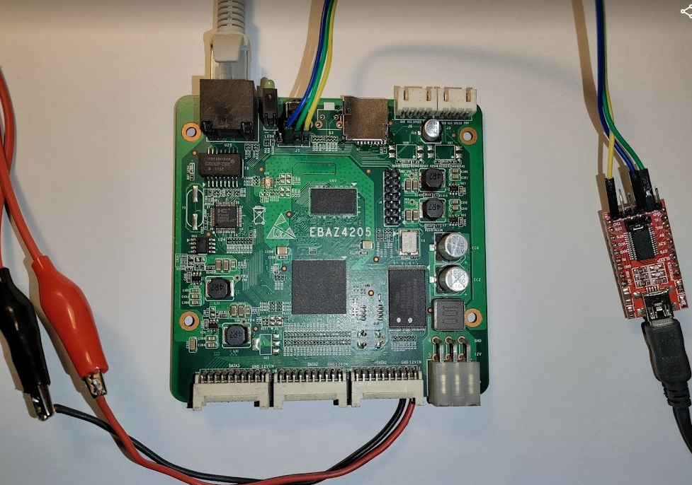
2. See the wirings.
- 3 wires RXD TXD and GND (blue, green and yellow in the picture) to a PC serial port configured at 115200bps, 8 bit, stop bit, no parity
- the 12V power supply directly soldered on the PCB (the 20 pin 2mm connectors will arrive from China at the end of August)
- the Ethernet cable to the home router
3. follow the instructions of xjtuecho/EBAZ4205 at paragraphs:
- "Reset the root password of built-in linux" and
- "Shut down the BTC miner program"
4. Edit /etc/network/interfaces and uncomment only:
auto eth0 iface eth0 inet dhcp
In this way you enable the ethernet port and a DHCP client on it to obtain an IP from your router (You do have a router with DHCP, don't you?)
5. Connect an ethernet cable to the ethernet port and then
reboot
6. I didn't want to buy an expensive JTAG programmer compatible with XILINK devices so I opted for this solution ft2232_to_digilent_jtag that transforms a FT2232 USB double UART into a double device:
- XILINX JTAG programmer
- UART
Now that you successfully checked your EBAZ420 board, you can go on!
PROGRAMMING THE EBAZ4205 WITH XILINX VIVADO
I found it more difficult than expected. VIVADO, VITIS IDE but especially PetaLinux are very powerful and complex instruments and their learning curve is very steep for me.
After many attempts, I managed to get working this Vivado block design, using the HW SW IDE described in the next section.
This block design configure the EBAZ4205 to create a clock generator (8-200 MHz) with a frequency programmable with a linux program. The HW logic, Linux and the programming software all run on the Zynq-7000 FPGA of the EBAZ4205. IMO this project lets me to setup and test all the different aspects (CPU/PS, PL, GPIO, Ethernet, Linux, boot from SD) for much more complex EBAZ4205 / Zynq-7000 projects.
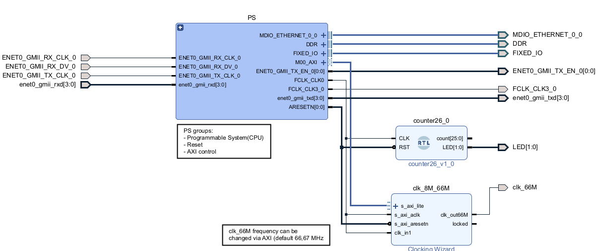
In this design please note that:
- the PS groups the IPs (Intellectual Properties) building the Programmable System logic, i.e. the CPU, the reset block, the AXI block and the Ethernet block
- the PS outputs the 25MHz FCLK_CLK3_0 to the pin U18 that in the EBAZ4205 is connected to the 25MHz Ethernet chip input. Without this clock the Ethernet port won't work!
- the PS outputs the 50MHz FCLK_CLK0 going to:
- a 26 bits counter to divide the 25MHz clock and flash slowly (~0,5 seconds) the two red and green LEDs
- a Clocking Wizard IP (clk_8M_66M) that outputs a programmable clock clk_66M (10 - 200 MHz) using a PLL
- the clk_8M_66M frequency is programmed by AXI. See the connection between the PS M00_AXI and the clk_8M_66M s_axi_lite
GLOSSARY
| NAME | DESCRIPTION | |
|---|---|---|
| PS (Processing System) | The CPUs (yes, they are 2) hosted inside the ZYNQ-7000 chip. In EBAZ4205 it can work alone, but without Ethernet. | |
| PL (Programmable Logic) | The digital logic programmed inside the ZYNQ-7000 FPGA. In EBAZ4205 it cannot work without PS, because the main clock is supplied by PS. | |
| "Standalone" (or "baremetal") app | Some software (written in C or C++) running on the Zynq PS without any Linux operating system. The peripheral drivers (Ethernet, UART, your PL block design, PS/PL interaction ...) are generated by Vitis | |
| Linux app | Some software (written in C or C++) running on the Linux operating system. The peripheral drivers (Ethernet,... |
 Tobias Rathje
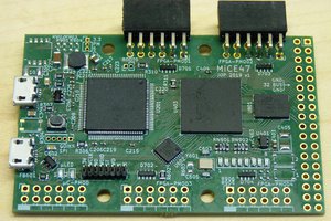
 Chance Reimer