 Lithium ION
Today we are going to make a minimal pressure sensor integrated with temperature sensor. This pressure sensor is also able to measure the approx. altitude level. The main idea is to make it simple and to keep the PCB as small as possible. There are many temperature sensors are available in market which offers a lot more precision level, but I choose BMP280 for the project. It is digital pressure and temperature sensor. Which also allows us to for a little bit of whether forecasting. And the size of sensor is very small (2 x 2.2x 0.95 mm), so it can be used in applications like smart watches, mobile phones, GPS, health care devices and other Nano embedded systems.
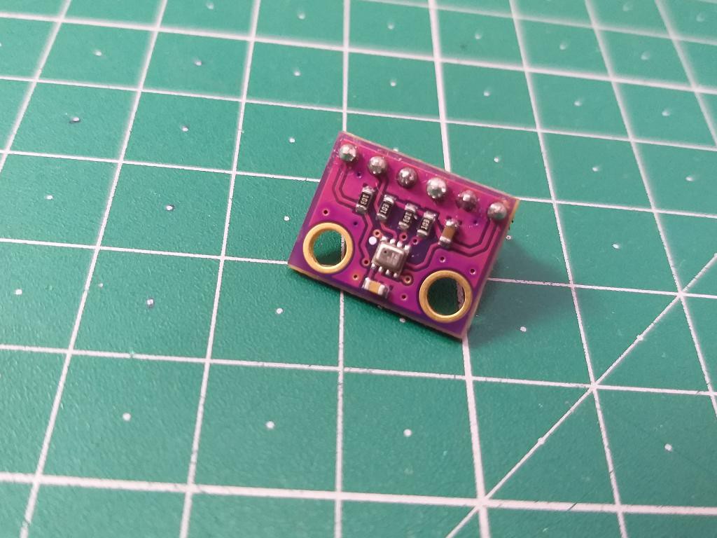
BMP280:
The BMP280 is an absolute barometric pressure sensor especially designed for mobile applications. The sensor module is housed in an extremely compact 8-pin metal-lid LGA package. As the successor to the widely adopted BMP180, the BMP280 delivers high performance in all applications that require precise pressure measurement. The BMP280 operates at lower noise, supports new filter modes and an SPI interface within a footprint 63% smaller than the BMP180. This sensor is developed by BOSCH technologies and you can Download the original datasheet from here.
Features:
Pressure range 300 to 1100 hPa (-500/+9000 meters range from sea level)
Temperature range 40-to-85-degree Celsius
Current consumption is 2.7uA @1Hz
Communication protocols: SPI and I2C
BMP180 and BMP280 are perfectly suitable for applications like floor detection since both sensors feature excellent relative accuracy is ±0.12 hPa, which is equivalent to ±1 m difference in altitude. The very low offset temperature coefficient (TCO) of 1.5 Pa/K translates to a temperature drift of only 12.6 cm/K.
Components Required:
Arduino Nano
BMP280 sensor
SSH1306 OLED display
5V power supply
Custom PCB from PCBWAY
Circuit diagram:
I choose I2C for the BMP280, my OLED also works on the same protocol. I interfaced both of them using the single I2C lane because of different address. BMP has I2C address of 0x76 and OLED has 0x3C. You can check the 12C address using the scanner programmer given in the description.
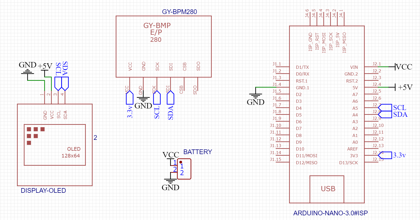
Our sensor works on 3.3volt level and OLED works on 5v. Arduino has onboard 3.3v available so need to worry about external regulators. Connect the power pins first, then connect Pin SCL to A5 of the Arduino and SDA to A4. The whole system can be powered using a 5v power supply or 9v battery. The current consumption of the sensor is very less in order of 2.7uA @ 1Hz sampling rate. You can also eliminate the display, the readings can be displayed on serial monitor of the Arduino IDE.
PCB designs:
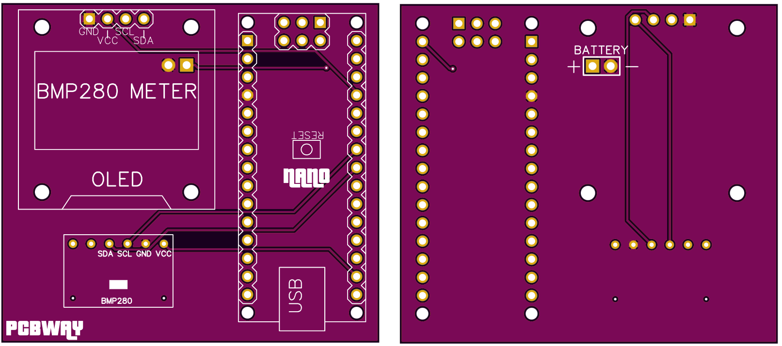
The project has a very few wires but for the daily usage making a PCB is good Idea. So, I turned by idea into a schematic and then into a PCB. You can download the PCB Gerber files from here. I am using PCBWAY PCB prototype service for a long time. Honestly, PCBWAY is the best PCB manufacturer and never compromise with the product quality. You can get 5pcs of 2layer PCB in just $5. Register now to PCBWAY to get new user discount coupons.
Code:
Get Serial monitor code from here. It doesn't require external display to show values.
#include <Wire.h>
#include <SPI.h>
#include <Adafruit_BMP280.h>
#include <Adafruit_GFX.h>
#include <Adafruit_SSD1306.h>

#define OLED_RESET -1
Adafruit_SSD1306 display(128, 64, &Wire, OLED_RESET);

#define BMP_SCK  (13)
#define BMP_MISO (12)
#define BMP_MOSI (11)
#define BMP_CS   (10)

Adafruit_BMP280 bmp; // I2C
//Adafruit_BMP280 bmp(BMP_CS); // hardware SPI
//Adafruit_BMP280 bmp(BMP_CS, BMP_MOSI, BMP_MISO,  BMP_SCK);

void setup() {
  Serial.begin(9600);
  while ( !Serial ) delay(100);   // wait for native usb
  Serial.println(F("BMP280 test"));
    display.begin(SSD1306_SWITCHCAPVCC, 0x3C);
  display.clearDisplay();
  unsigned status;
  //status = bmp.begin(BMP280_ADDRESS_ALT, BMP280_CHIPID);
  status = bmp.begin();
  if (!status) {
    Serial.println(F("Could not find a valid BMP280 sensor, check wiring or "
                      "try a different address!"));
    Serial.print("SensorID was: 0x"); Serial.println(bmp.sensorID(),16);
    Serial.print("        ID of 0xFF probably means a bad address, a BMP 180 or BMP 085\n");
    Serial.print("   ID of 0x56-0x58 represents a BMP 280,\n");
    Serial.print("        ID of 0x60 represents a BME 280.\n");
    Serial.print("        ID of 0x61 represents a BME 680.\n");
    while (1) delay(10);
  }

  /* Default settings from datasheet. */
  bmp.setSampling(Adafruit_BMP280::MODE_NORMAL,     /* Operating Mode. */
                  Adafruit_BMP280::SAMPLING_X2,     /* Temp. oversampling */
                  Adafruit_BMP280::SAMPLING_X16,    /* Pressure oversampling */
                  Adafruit_BMP280::FILTER_X16,      /* Filtering. */
                  Adafruit_BMP280::STANDBY_MS_500); /* Standby time. */
}

void loop() {
    display.clearDisplay();
    display.setTextSize(1);
    display.setTextColor(WHITE);

    display.setCursor(0,10);
    display.print(F("Temp. = "));
    display.print(bmp.readTemperature());
    display.println(" *C");

    display.setCursor(0,30);
    display.print(F("Pressure= "));
    display.print(bmp.readPressure());
    display.println(" Pa");

    display.setCursor(0,50);
    display.print(F("Altitude = "));
    display.print(bmp.readAltitude(1013.25)); /* Adjusted to local forecast! */
    display.println(" m");

    display.display();
    delay(2000);
}
Library issues:
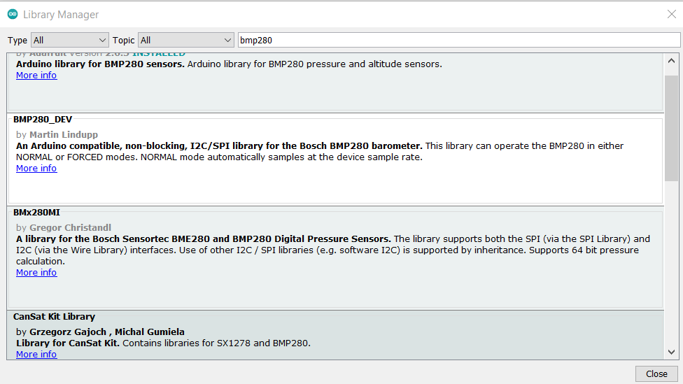
You can install the BMP280 library from Arduino IDE, from library manager under tools menu.
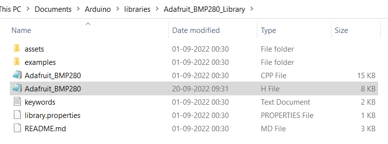
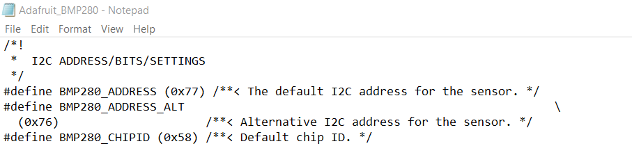
BMP280 adafruit library has some issues with I2C protocol, so if you are using I2C communication then change the address of BMP280 to 0X76 manually from h file.
Or you can download the proper library from here. No need to change the file if SPI protocol is used.
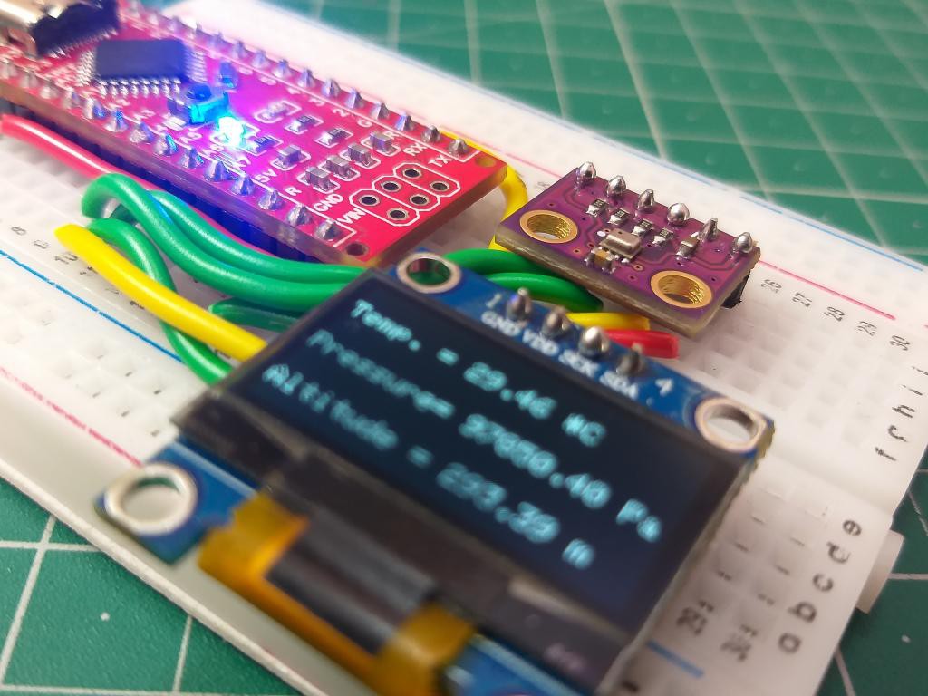
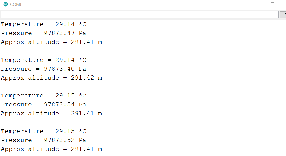
Demonstration:
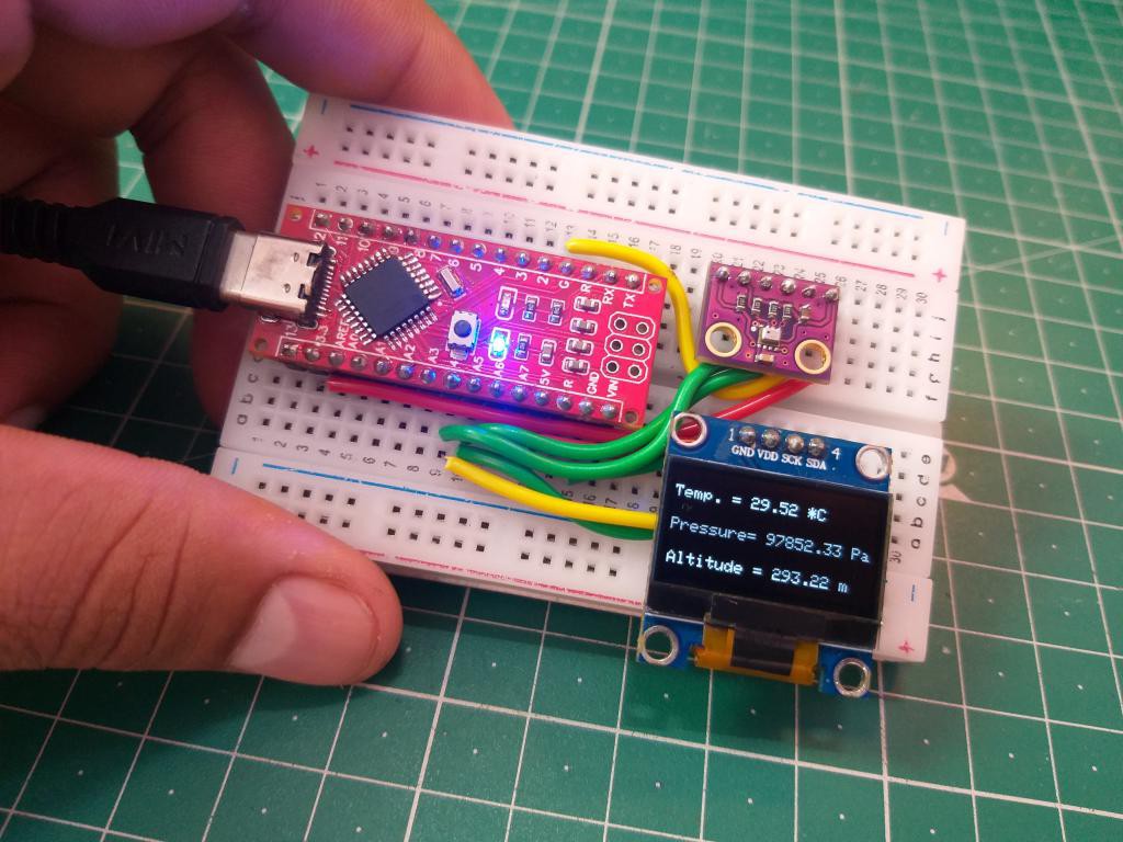
For demonstration purpose I mounted all the components on a breadboard. The two different codes are given above, you can choose as per hardware. I am using a small OLED to display the values and here are the results.
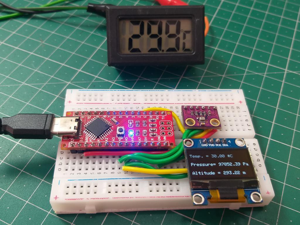
The sensor is very accurate and you can also adjust the altitude readings as per your area. The readings are allowed to update after every second.
PCBWAY is best Manufacturer:
I made my own Arduino Nano microcontroller board using PCBWAY prototype service. I designed this PCB and then ordered it from PCBWAY. The ordering process is quite easy just fill the parameters of board choose color, thickness and type of finishing and then add it into cart.
Upload your Gerber files and you will get the quote within 1 hour, You can discuss the specifications with the PCBWAY engineering team. For these PCB layouts I choose red color, HASL finishing and I got 5pcs these amazing quality boards just in $5. Visit PCBWAY from here and see full article on Arduino making from here.