 Lithium ION
In this tutorial, we will build a project with OLED to display different images/ QR using Arduino. Using this you can display any static image on the screen. First, we will modify the image using photo editor and then convert into Arduino compatible hex code. Which then required to light up the single pixel accordingly to the code.
The same approach can be used to run a video on this display, which we will try to cover soon. The difference is that picture is static but video uses a 25 frames per second system which can be lowered down to 20 as per Arduino compatibility. Here I have some converted hex code images of Virat Kohli, Dhoni and Rohit Sharma from Indian cricket team. For now, I am covering single QR displaying method and you can find the video for the picture display. The concept is same but let’s know about QR first.
QR Code:
The quick access code is an encoded form of the data, which is not readable by humans. The basic QR code has main components like:
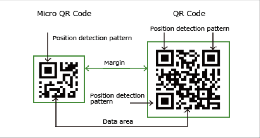
1) Alignment boxes: This gives the orientation in which data is organized in QR. It helps the scanner to be accurate whatever is the direction and orientation of the scanning.
2) Size of the code, QR version information, Timing patterns and format info.
Required elements:
1) Image file of QR
2) Arduino Nano
3) OLED display
4) 9V battery
5) PCB shield from PCBWAY
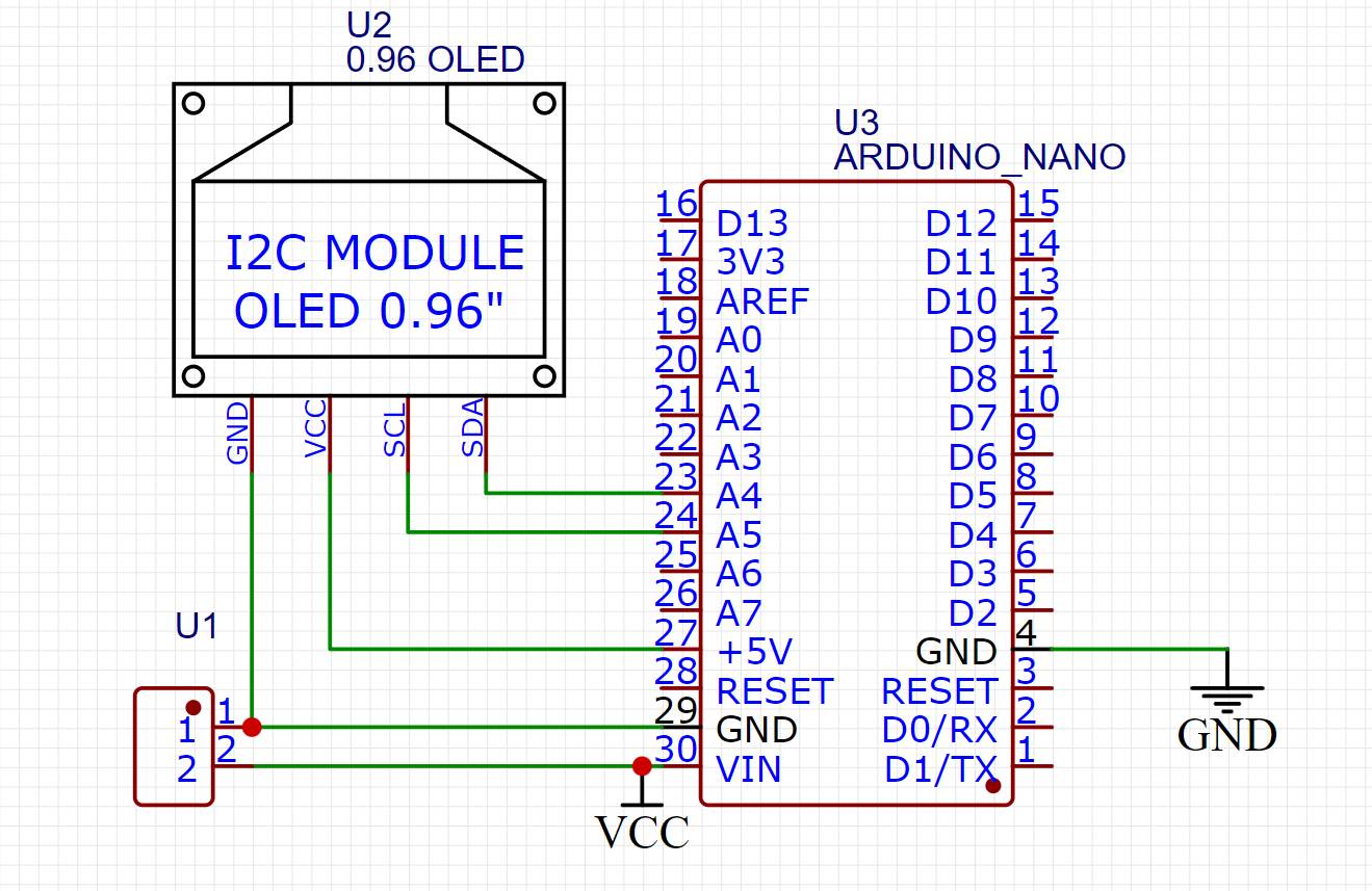
Circuit diagram and working principle:
Here I have 12C OLED 0.96-inch display, which has a resolution of 128x64. It is connected to Arduino through I2C interface which use 2 power wires, 1data and 1 clock. SCL goes to A5 of the Arduino and SDA to A4. Whole of the circuit can be power using a 9v battery or 5v adapter.
It is very easy to do all the connection and no any external component is required. The main idea is to get the code out of the image file. First of all, get we will get the QR of the respective used link. It is downloaded in PNG format, then compress the QR to BMP file to 64x64 pixels. This file is used to get the Arduino code in the hex format which will lit up every pixel respectively.
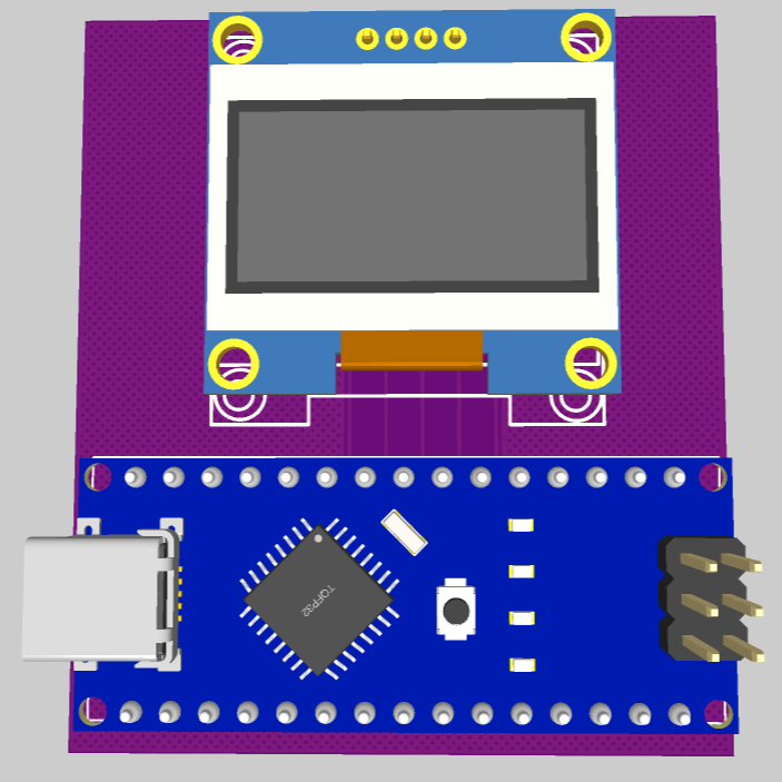
PCB shield:
I made the PCB using Altium designer and then converted the files into PCB and download the Gerber files. You can also download the same files from here. PCBWAY is offering the best prototyping service in just $5 for 5pcs of double layered boards.
To Order visit PCBWAY from here > Update the board of size > choose color, material and finishing type > save the settings to cart > upload the Gerber files and checkout in minutes. The files will be examined by PCBWAY engineers and then confirmed before the production.
Getting code from Image file:
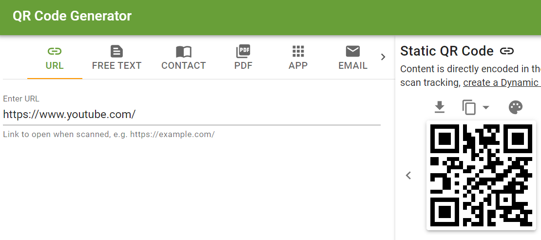
1) Let’s generate QR, paste your link and download the QR in PNG format from this website.
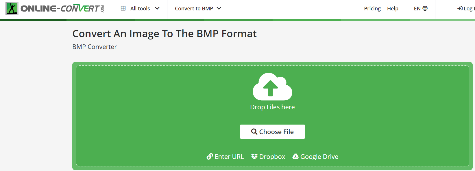
2) Compress the PNG file to BMP using this website tool and set the pixels 64x64 and keep the remaining same.
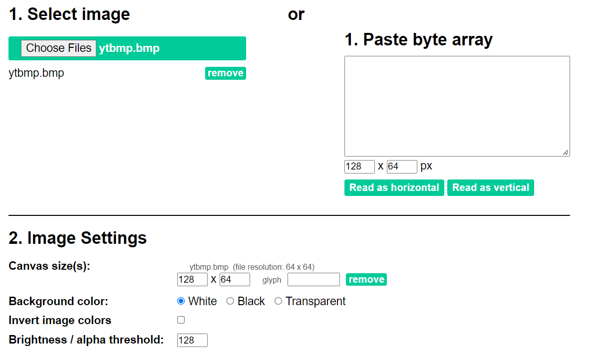
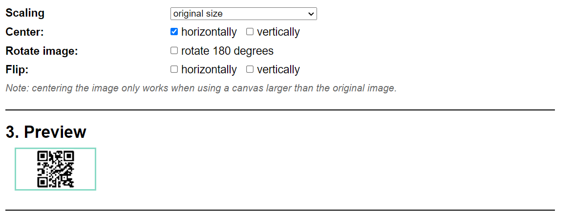
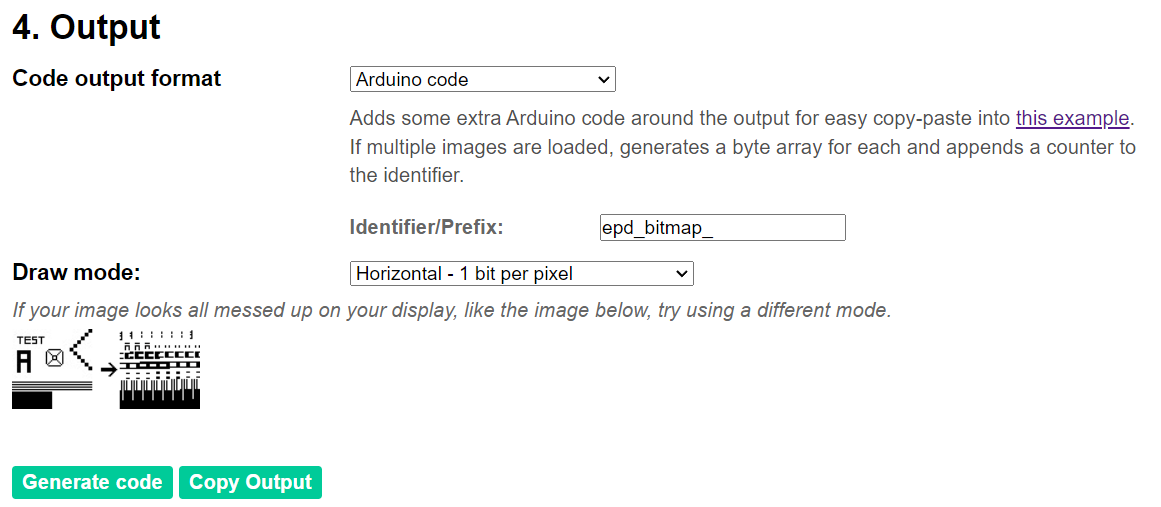
3) Upload this BMP file to Code converter (Image to CPP) made by my friend and then copy the piece of code. Keep the size 128x64 for LCD, brightness to 128, scaling to original and center to horizontal and go to that website from here.
4) Now keep the code settings to Arduino and generate the code.
5) Copy the code and remove unwanted lines and put it into main program.
Main code file:
This one redirects to my own website, let's find out my website:
#include <SPI.h>
#include <Wire.h>
#include <Adafruit_GFX.h>
#include <Adafruit_SSD1306.h>
#define SCREEN_WIDTH 128
#define SCREEN_HEIGHT 64

Adafruit_SSD1306 display(SCREEN_WIDTH, SCREEN_HEIGHT, &Wire, -1);


// Bitmap of  Image
const unsigned char My_QR [] PROGMEM = {
  0xff, 0xff, 0xff, 0xff, 0xff, 0xff, 0xff, 0xff, 0xff, 0xff, 0xff, 0xff, 0xff, 0xff, 0xff, 0xff,
  0xff, 0xff, 0xff, 0xff, 0xff, 0xff, 0xff, 0xff, 0xff, 0xff, 0xff, 0xff, 0xff, 0xff, 0xff, 0xff,
  0xff, 0xff, 0xff, 0xff, 0xe0, 0x00, 0x1c, 0x03, 0xc3, 0xf8, 0x00, 0x07, 0xff, 0xff, 0xff, 0xff,
  0xff, 0xff, 0xff, 0xff, 0xc0, 0x00, 0x18, 0x01, 0x83, 0xf8, 0x00, 0x03, 0xff, 0xff, 0xff, 0xff,
  0xff, 0xff, 0xff, 0xff, 0xc0...
Read more »
 tomwsmf
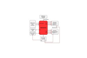
 kutluhan_aktar
 RobsonCouto