 kelvinA
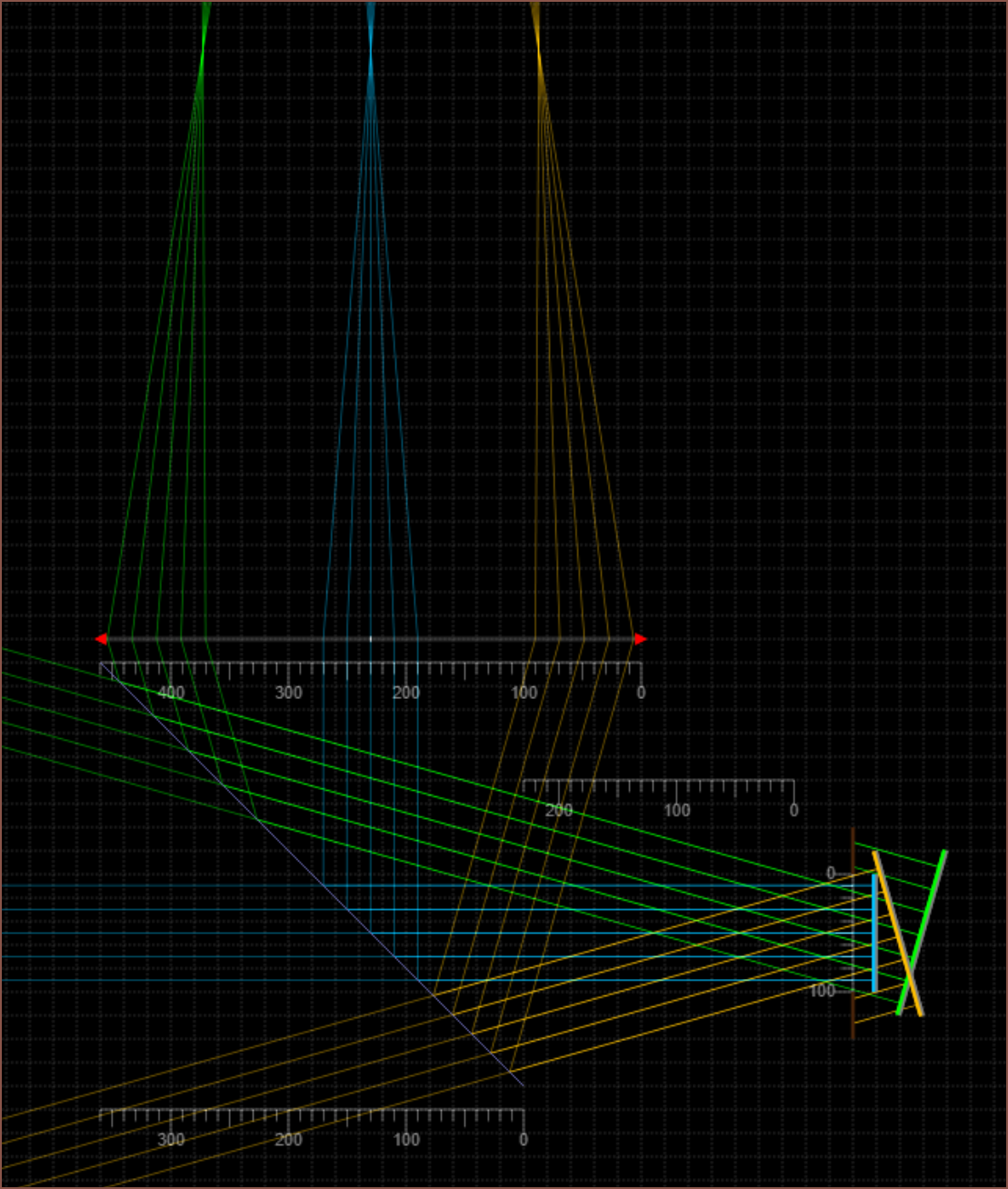 So, by enabling "simulate colours" and aligning 2 "beam"s to have the same angle as +/- 16 degree (and blocking out the excess), I was able to get rays that look like the optical rays diagrams I've been seeing in AR diagrams such as this one I've recently seen:
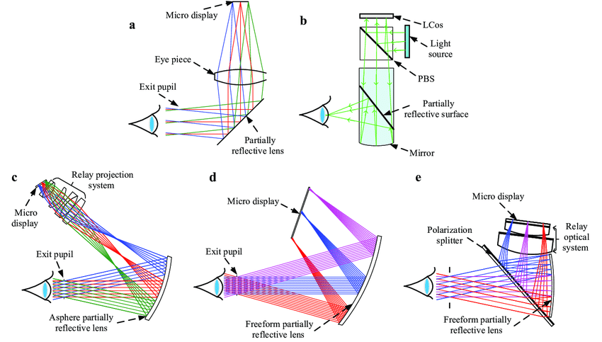
Now, I'm estimating that this is used to see both FOV and focus, along with confirming the eyebox.
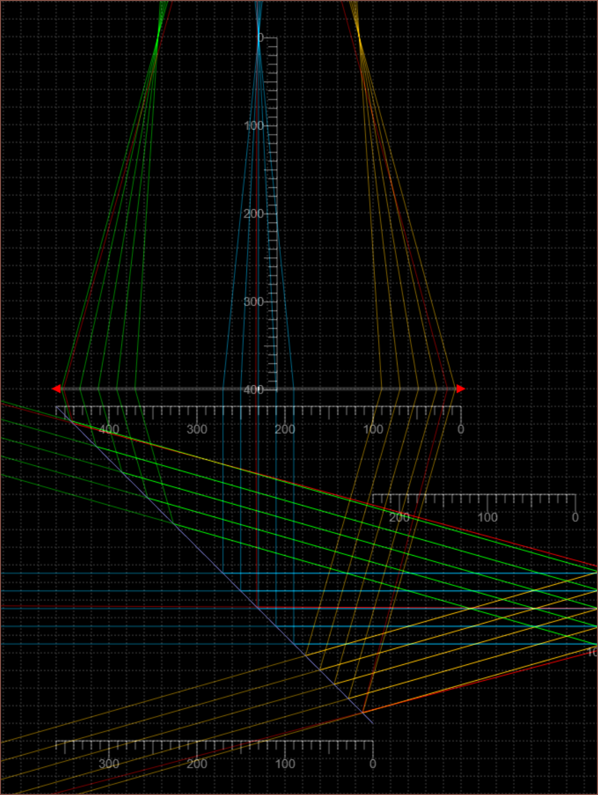
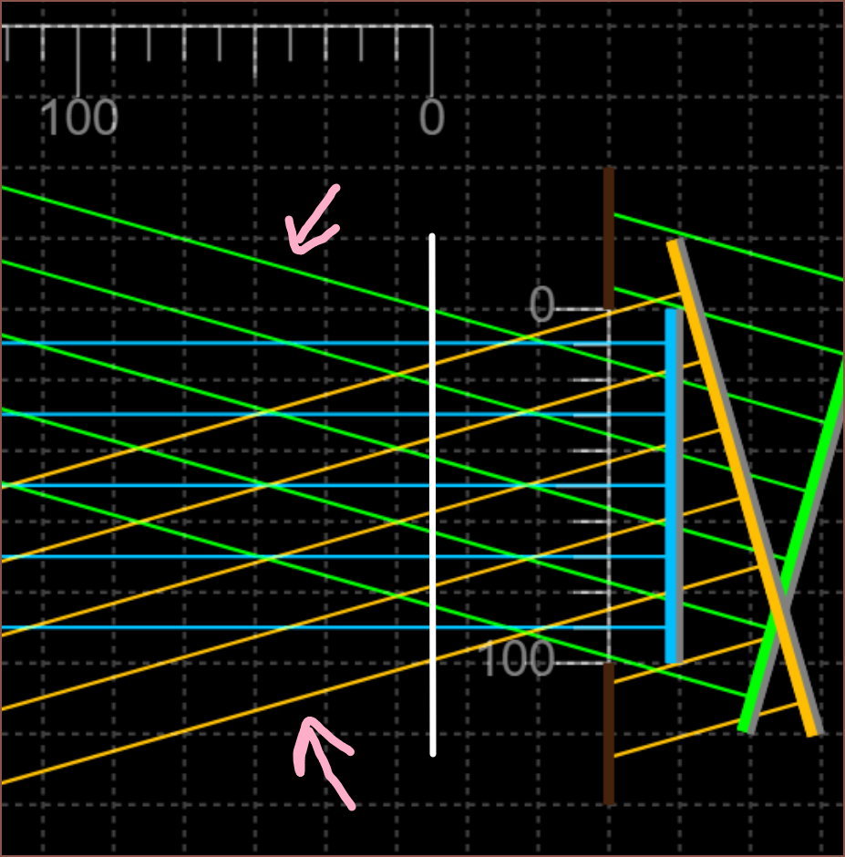 The white line is where the eye starts. I'm going for a 10mm eyebox (the scale in these simulations is 10 units : 1mm) and the lines pointed to by the arrows is the cone of light I care about.
 As you can see, each slightly different colour set of rays are parallel. This means that the intended focus is infinitely far away. I've also used colours slightly different from RGB to prevent personal confusion.
 I think that the focus point is juuuuust behind (or infront) of the locationwhere the rays merge together into a point. This is because the pixel isn't an infinitely small point. The rays are also used to see the distance and size of the screen when focused at infinity. This is a notable difference to where I thought this location would be. Let me add a red beam to show you what I was doing before:
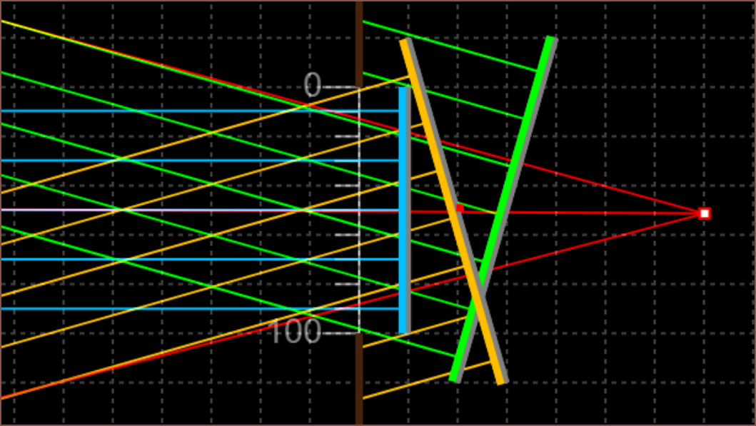
It's slightly misaligned but it's close enough for a description.
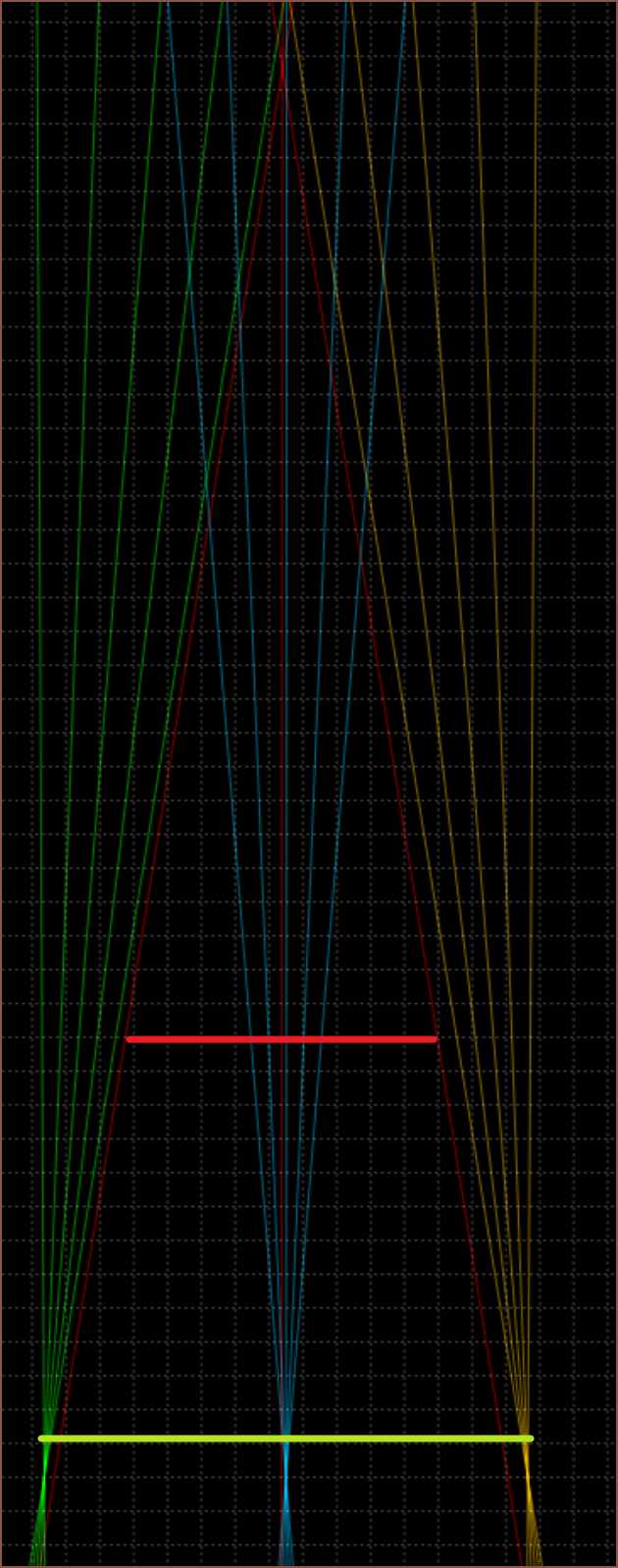 The lime green line is a screen with the right focus but wrong size, and the red line is the 18mm 2560px display size. Looking at where the actual FOV lines are, I would've misplaced this even further back. So, technically, the screen at the red location would've taken up my entire view, but that would've only been with 1 out of the 5 rays. The other 4 rays, likely originating from a black wall or something that isn't the screens active area, would make the edges mostly wall. At the same time, the centre is getting light from a wide part of the screen, so all those rays would get blended too. What would this look like? A stereotypical blurry blob of light that blur-fades into darkness the closer to the edges I look.
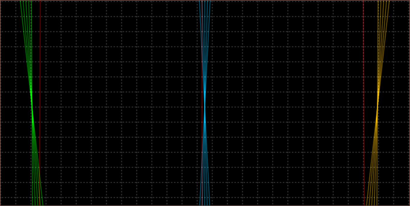
The below image is with a lens focal length of 80 instead of 50. In the first simulation, I would've thought that this would collect parallel rays (red) but no there's a (wider than the lens) location where an item would be in focus:
 Well I've got some lenses so I might as well see if my hypotheses are correct or not. The below is F-30 and indeed if I look though the lens I actually have with my eye set to infinity, it just looks like a blur at any distance:
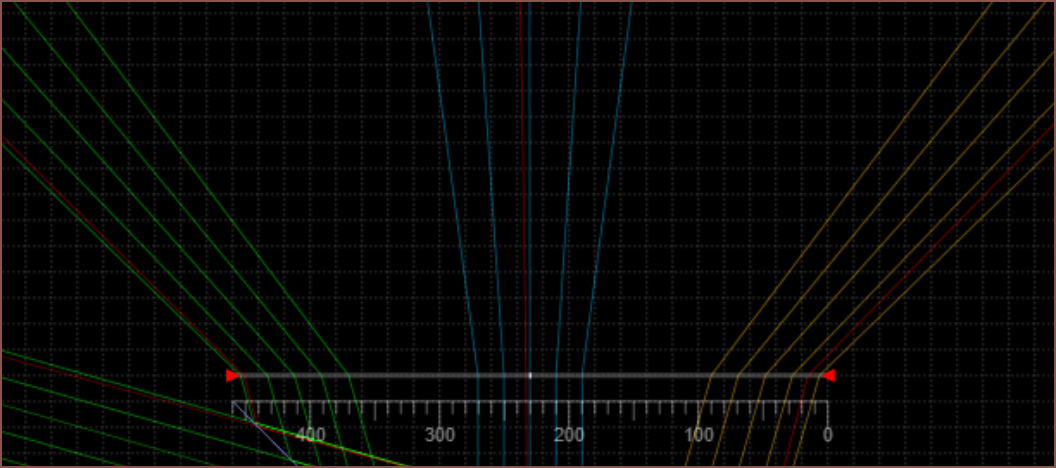
What about F40?
 Allegedly, if my eye is 60mm away from the lens and the image source is 40mm behind it, I should be able to see it at focus=infinity.
Wow. I just looked using the placeholder 40mm beamsplitter prints and can indeed confirm that the focus, FOV and eyebox are probably correct. Magical. No... scientific!
Discussions
Become a Hackaday.io Member
Create an account to leave a comment. Already have an account? Log In.