One day my oscilloscope died. I had picked up the Raspberry Pi 400 a year earlier with the vague intent of creating a cyberdeck - this was the sign to do it.
Goals:
- Folding
- Battery powered
- Potentially useful for something
- Large screen
- Able to be dismantled
- aesthetic
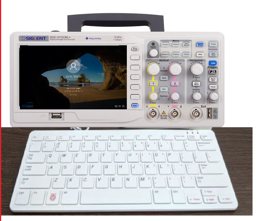
Concept:
(Most of) Parts:
- Siglent SDS 1072CML+ (non-booting)
- Raspberry Pi 400
- LimeSDR
- USB Hub
- Panel mount ethernet socket
- Panel mount USB A female -> USB A male
- Panel mount USB B female -> USB A female
- 4x Panel mount BNC -> SMA
- Panel mount DSUB-9 (from a PC PCI expansion slot plate)
- USB 3.0 extension cable
- Micro-HDMI -> HDMI -> Mini HDMI
- External USB powerbank (not shown)
- HDMI -> LVDS adapter (e.g. https://www.aliexpress.com/item/1005004307251919.html - not my seller, multiple sources available)
Raspberry Pi 400 Mounting Mechanism:
From Jeff Gerling's video (https://www.youtube.com/watch?v=OqpylxLhw98), I knew that the Raspberry Pi 400 has a large heatsink - far greater than the size of the PCB. I decided to drill & tap this heatsink for some M3 mounting bolts (go get yourself some taps, they are GREAT).
LimeSDR:
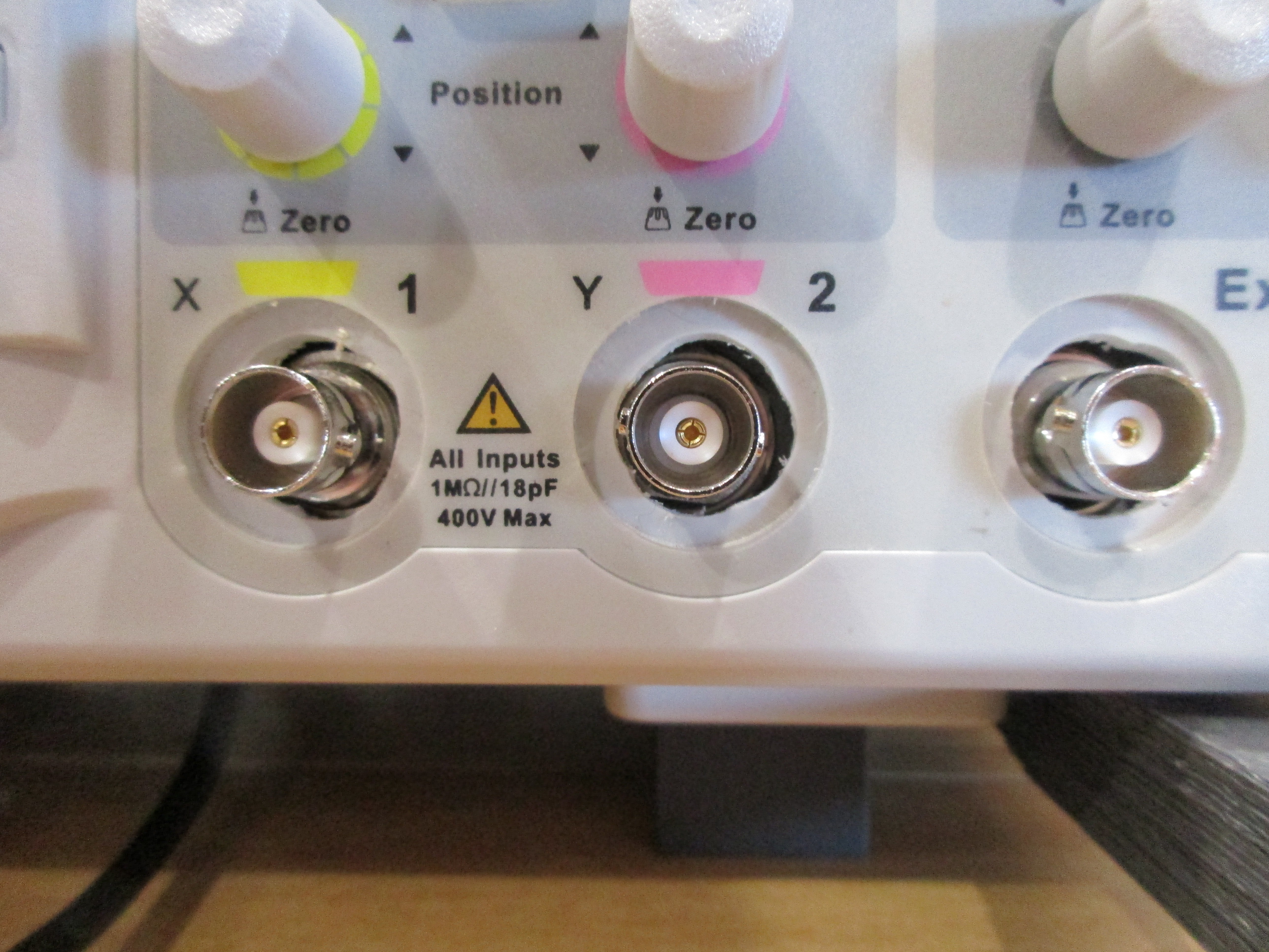
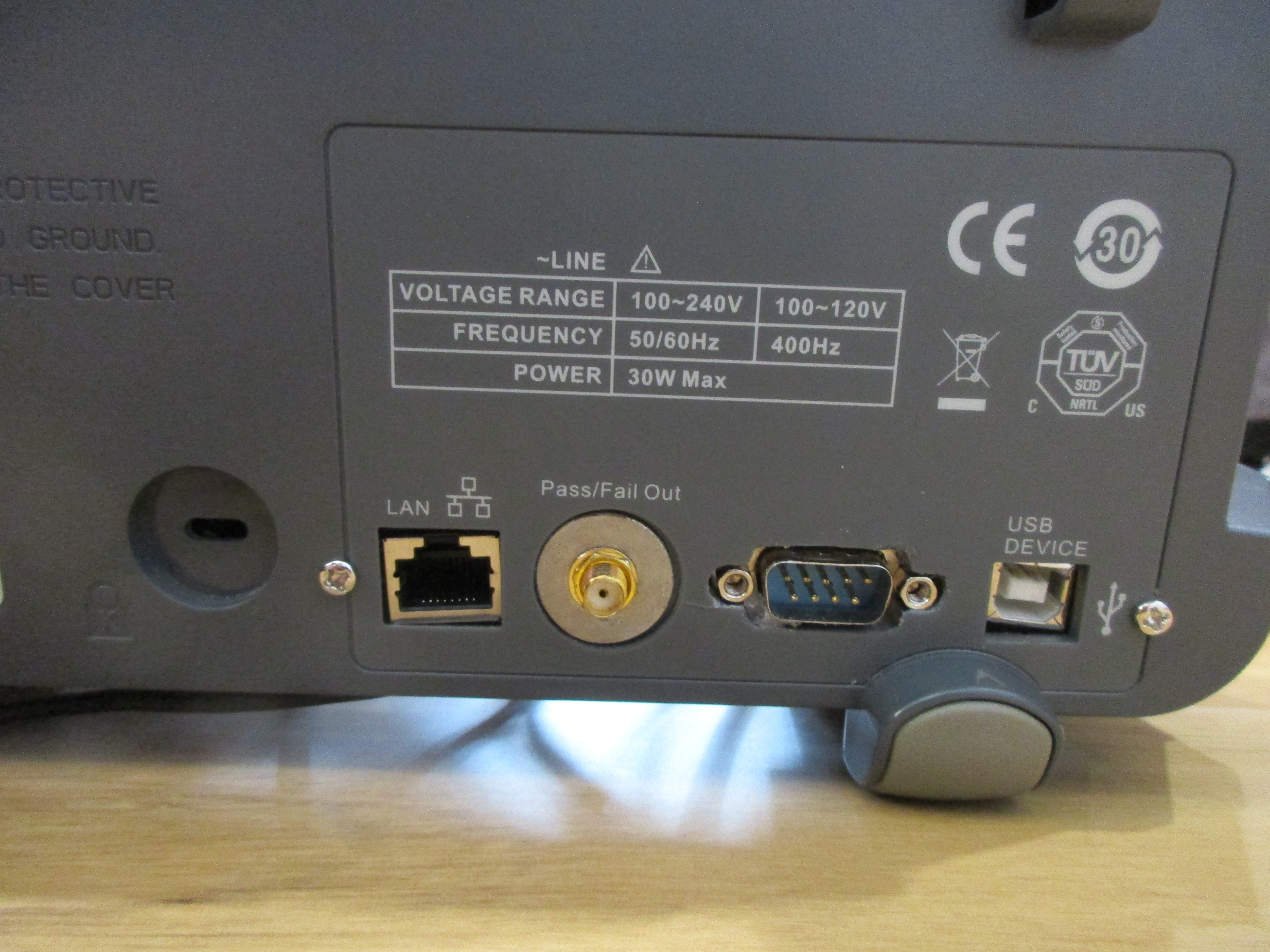
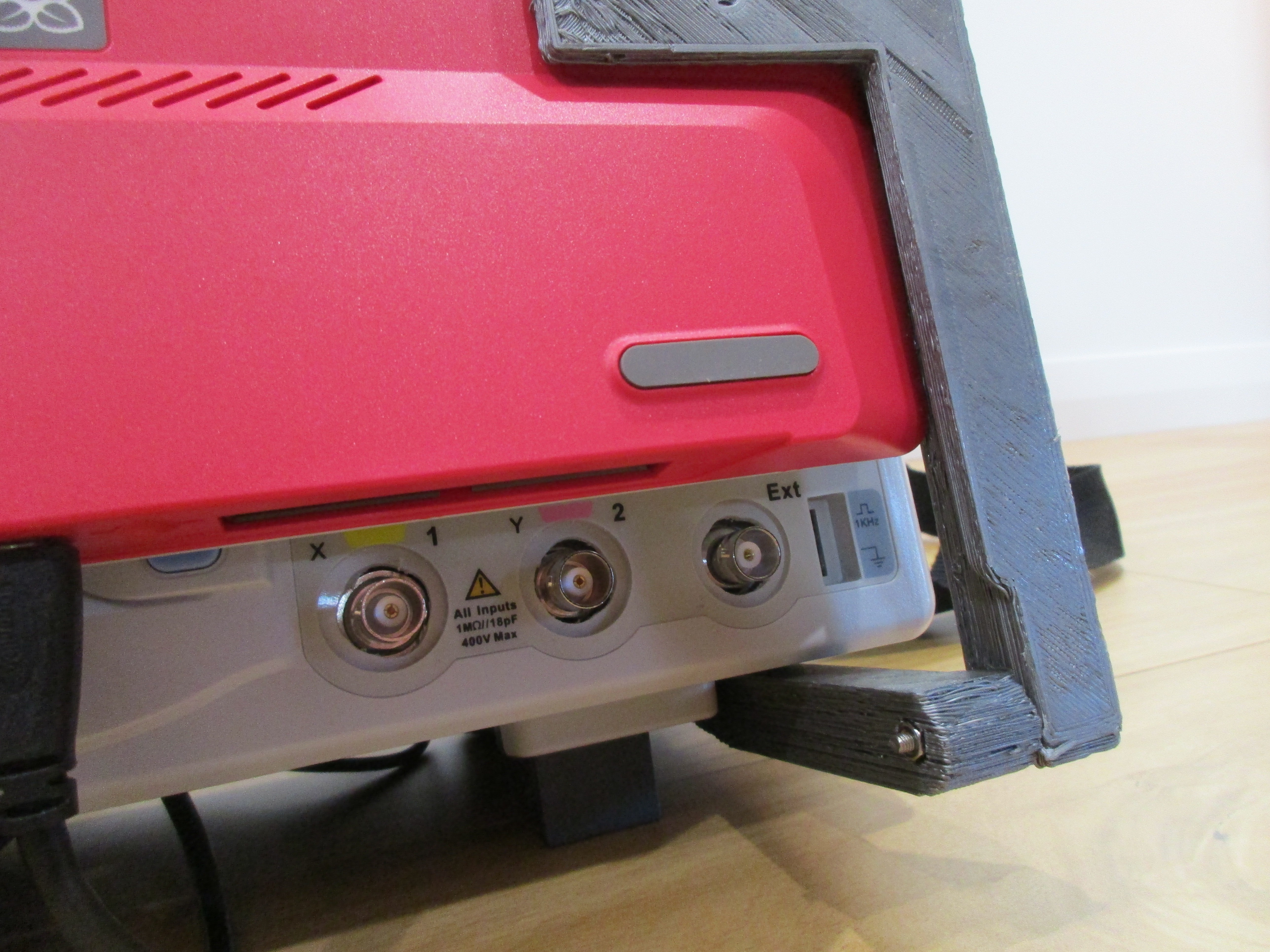
The LimeSDR is connected via USB3.0 directly to the Raspberry Pi 400. The two Oscilloscope inputs are connected to the channel 1 and 2 wideband inputs respectively. The front ext trigger is used as Tx1_1. The rear pass/fail port is a SMA connection, and is used as Tx2_1.
The LimeSDR is mounted in front of the fan, as active cooling is required. Adhesive aluminium heat sinks are applied to the LM chip, and the FPGA.
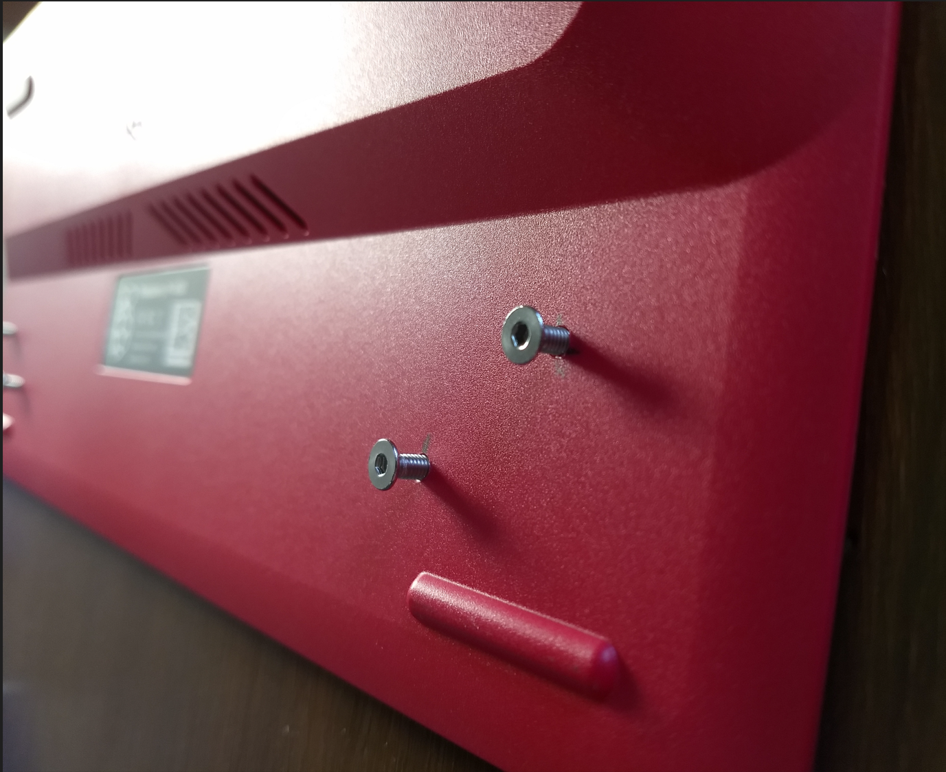
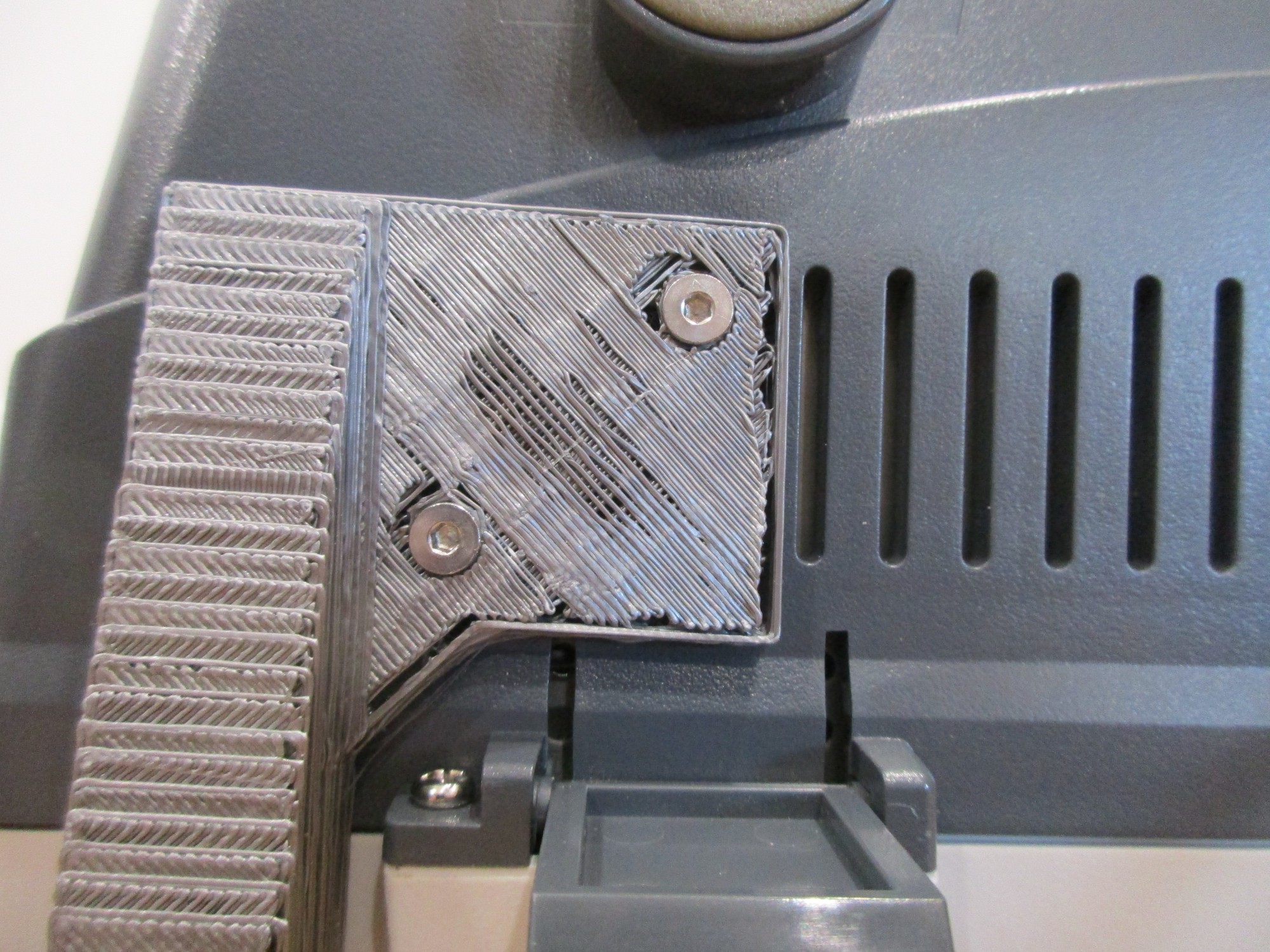
Mounting to Oscilloscope:
Uses M3x14 bolts into the plastic casing of the oscilloscope. These holes are tapped.
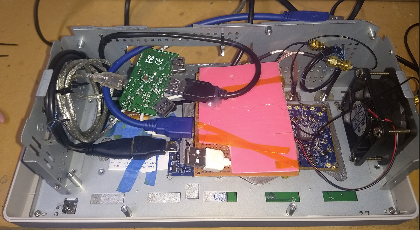
Internals:
All oscilloscope internals, barring control panel and screen are removed. LimeSDR is mounted on a 3D printed plate, directly in front of the fan. A power distribution board, made out of protoboard, is placed on top. This powers the fan and the LVDS/HDMI adaptor board, and is connected to the USB B socket on the rear. A separate power board is used to avoid over-currenting the Raspberry Pi 400.

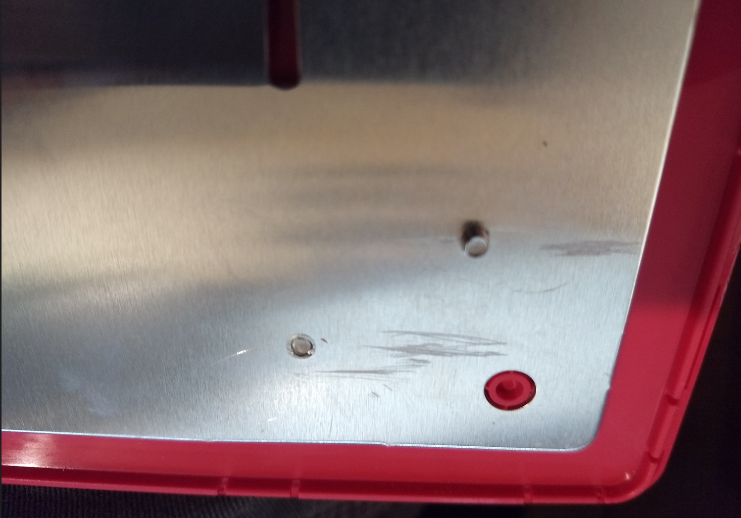
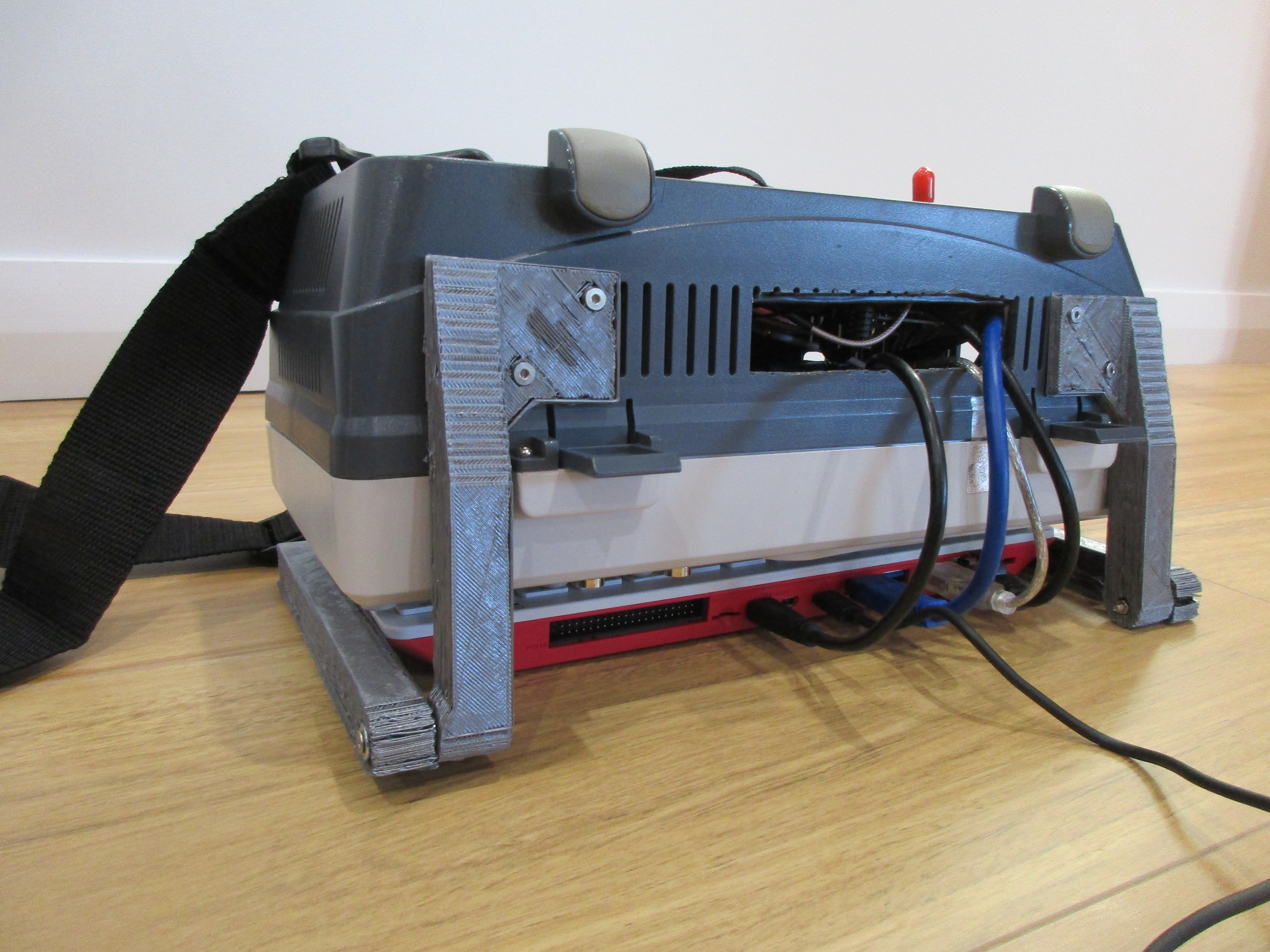
The cables are routed through a hole cut in the bottom:
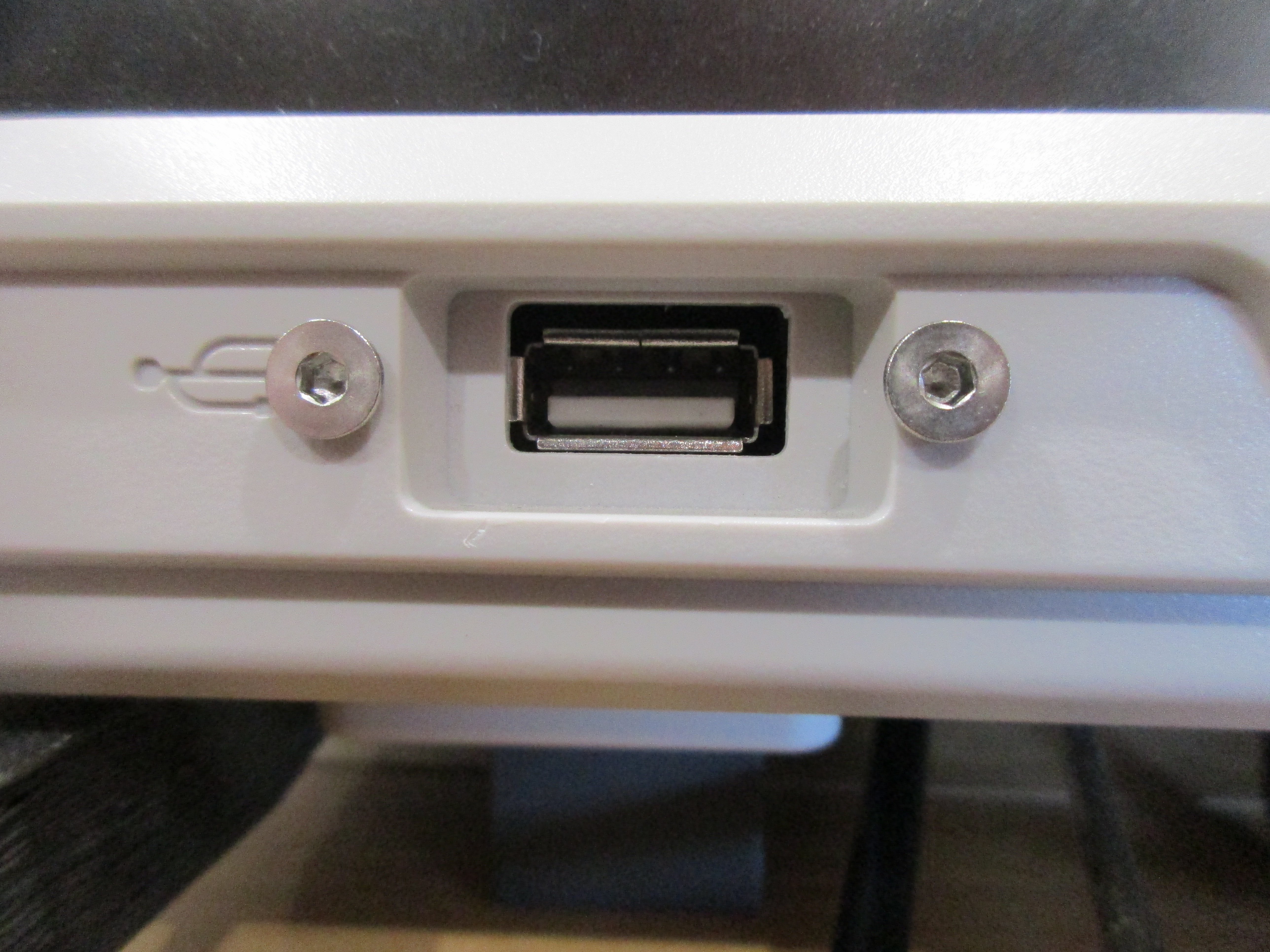
Ports:
Front USB is connected to an internal USB hub. Rear USB B is for power. Rear serial (DB-9) is connected to an internally mounted PL2303. Ethernet port is connected through to the Raspberry Pi 400 directly.
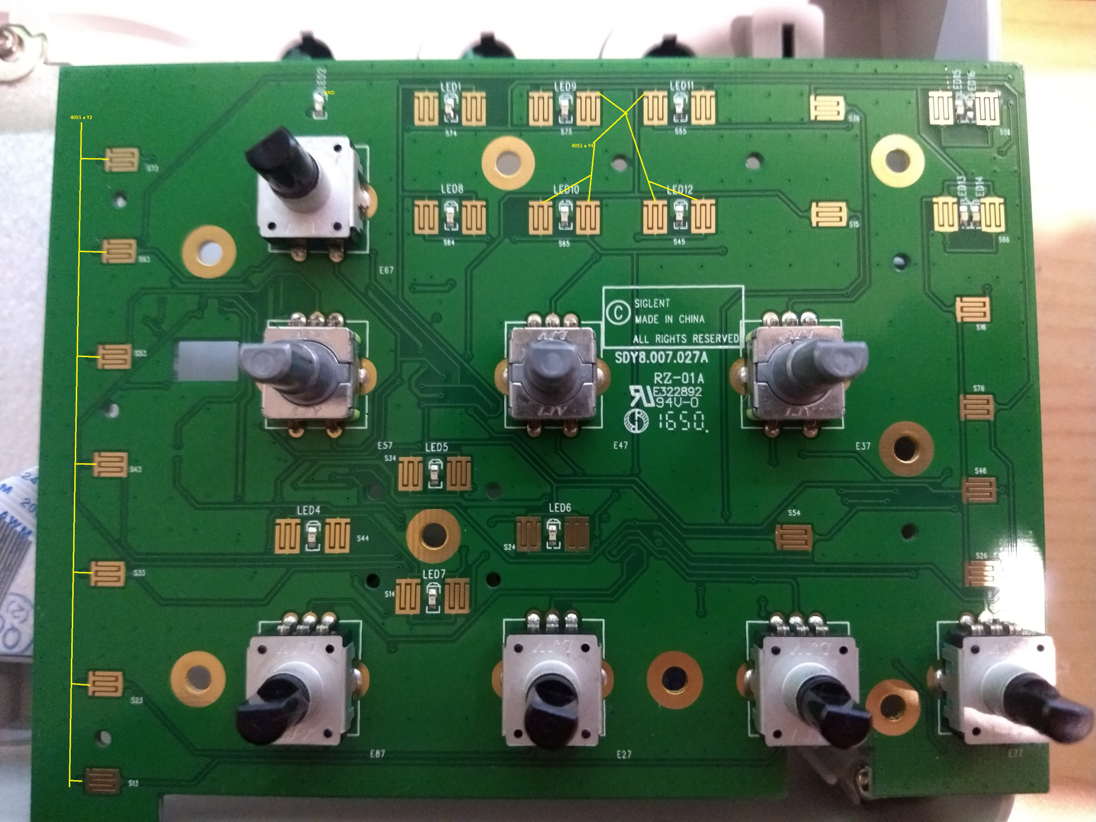
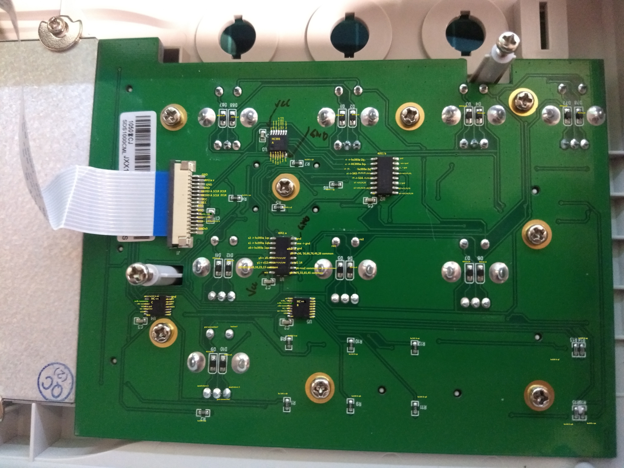
Oscilloscope Controls:
Intent is to use a STM32 as a USB HID to interface to the control board and dials on the front, as a combination of Mouse & Keyboard. Partial effort into reverse-engineering the board has occurred.
Seems to use some decade counters to multiplex the buttons, with some analog multiplexers to read.
It folds!:
 JohnJayMcKaye
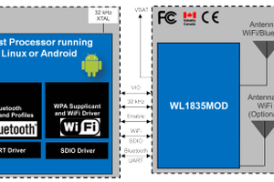
 John Basista
 Thomas