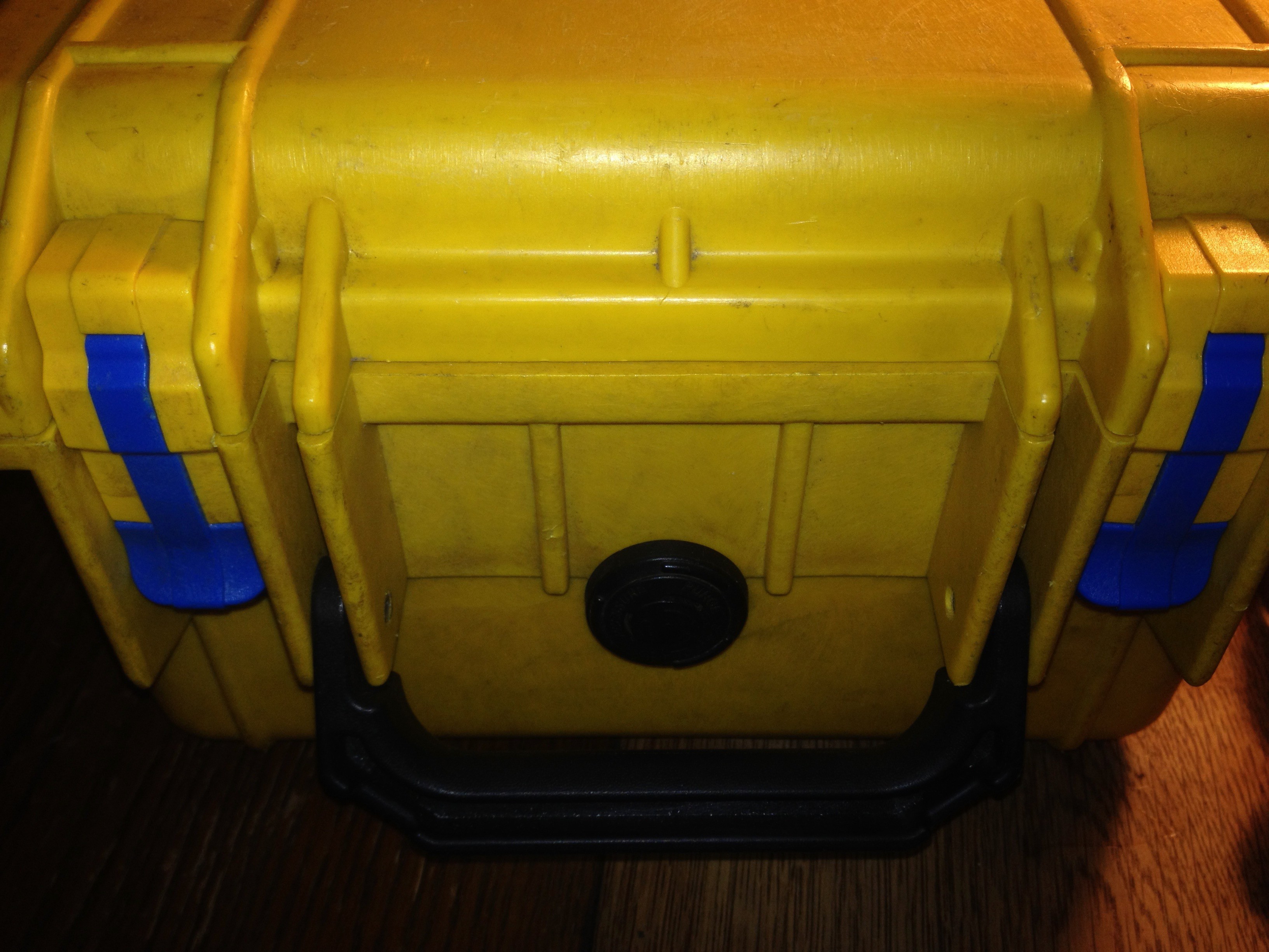
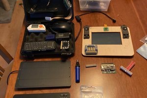
The case is a Peli 1300 "Protector" which I got second-hand from eBay. First task, cleaning off the original industrial labels (paint scraper + solvent) and then replacing the damaged handle and clips. (Part of the RS components order, along with the waterproof switch and USB sockets.)
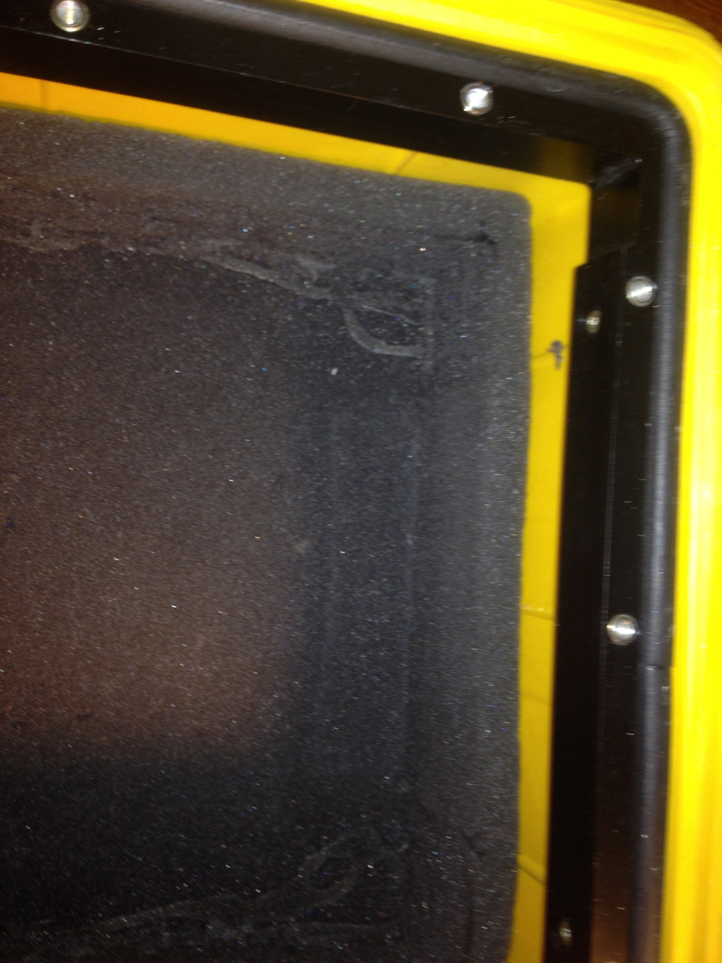
The original foam lining I've mostly left alone, I had to remove a divider, but that was it. I haven't modified the case in any other way, especially no extra holes, so when closed it is very waterproof. Next, again off eBay, I got a front panel mounting bezel and fitted that. It slides in to position and then grub screws hold it in place to the main case.
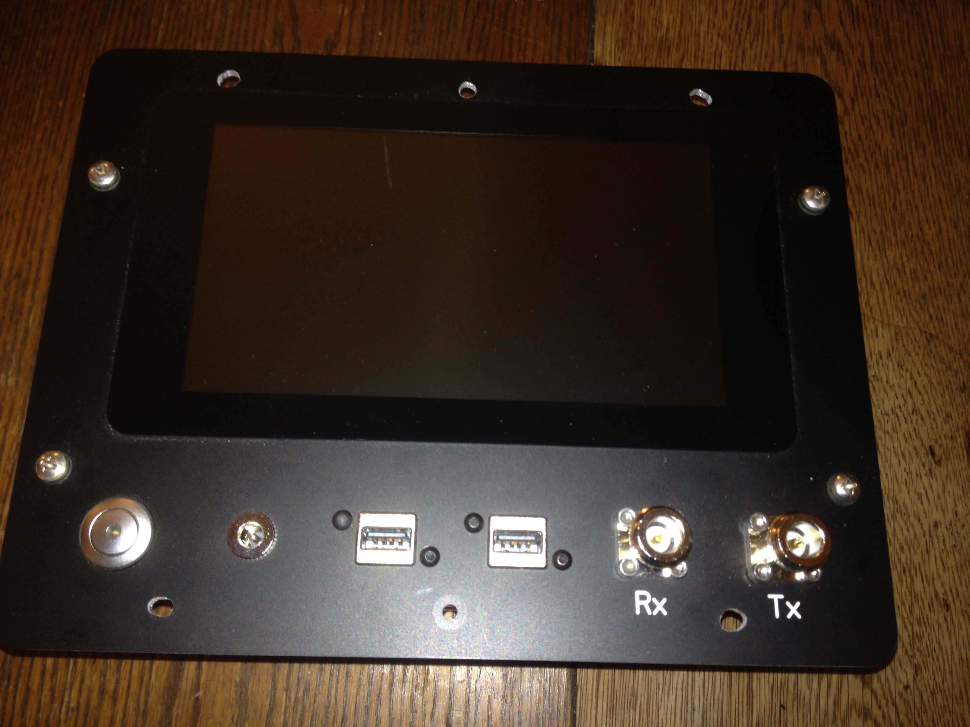
For the front panel I got the dimensions for the case and bezel from the Peli website, for the screen from RaspberryPi site and the USB sockets, switch, 5.5x2.1 socket and N-type connectors from RS datasheets. I designed the front panel in the FrontDesign website's own software and ordered it online in 3mm aluminium.
Then disaster struck!
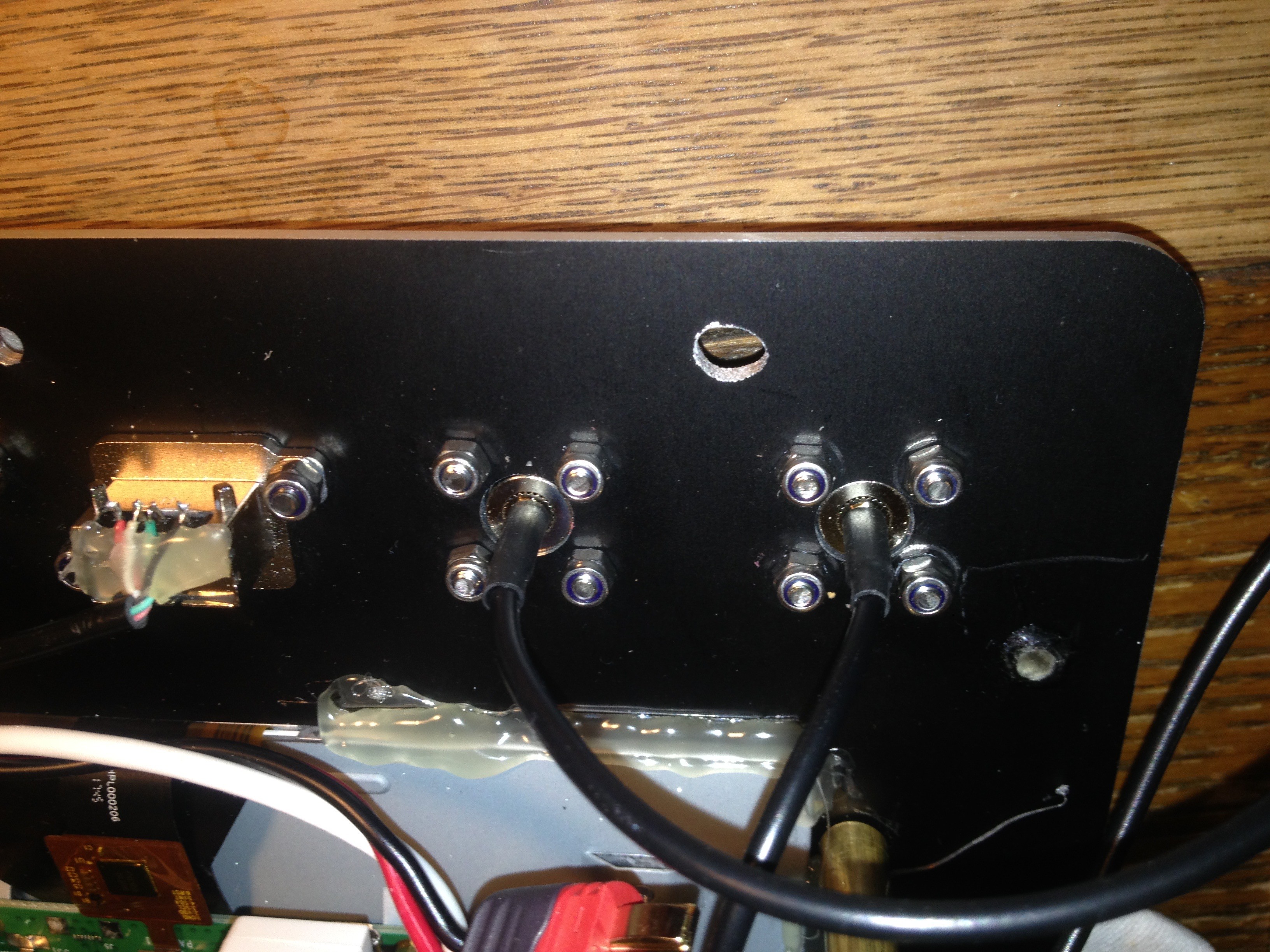
Either I'd placed the holes for bolting the panel to the bezel incorrectly, or the old bezel I'd got second-hand didn't match the current datasheet, but only the top and bottom center holes were correct. Some quality time with the Dremel enlarged the top row left and right holes out about 3mm, and the same for the bottom. The side holes were simply too far out of alignment to use. I wondered about tapping new ones in the bezel, but ended up just expoying bolt stubs over the holes as waterproof fakes. In addition, the main rectangle for the Raspberry Pi display was the correct size and placement (NB, it isn't symmetric!) but at the back of the screen there's a small ledge about 6mm wide, less than 1mm thick and most of the height of the screen on one side that means the screen didn't lie flat to the front panel. Back to the Dremel! Now I'd got the screen to fit and could bolt the front panel to the bezel.
Next step, I fitted the main rods to the front panel. These are 6mm brass tubes, 2mm hole, tapped M3 in each end. They are held to the front panel by M3 countersink head bolts that are hidden behind the edges of the screen.
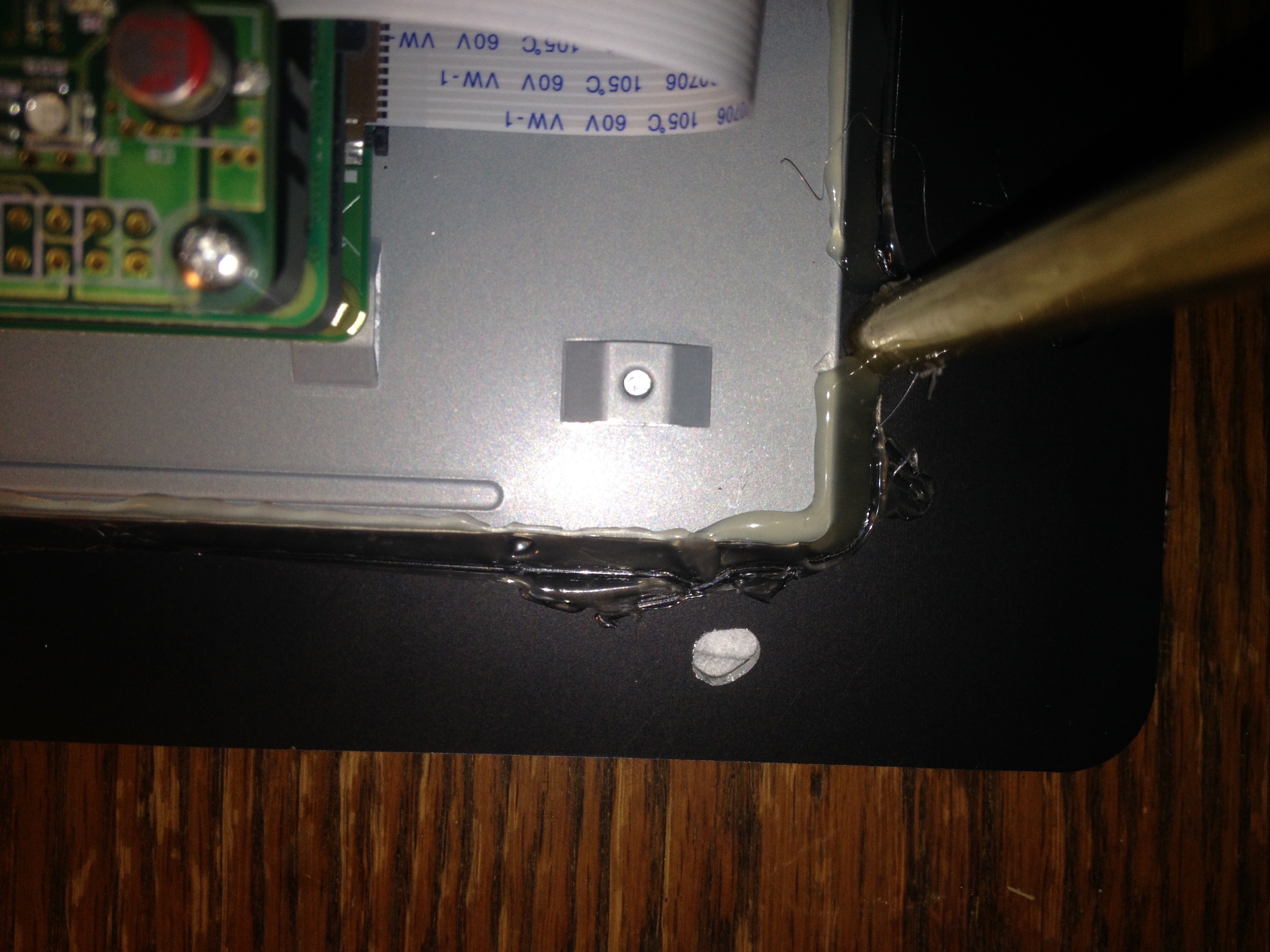
After these were fitted, the switch and sockets went in and finally the screen. The screen is held in place with hot melt glue! I was going to look for something more robust, metal strips and pusher screws, but after doing the glue for a bit of water protection it was quite firm enough.
The back of the unit is just a 3mm metal sheet, drilled to bolt to the other end of the rods.
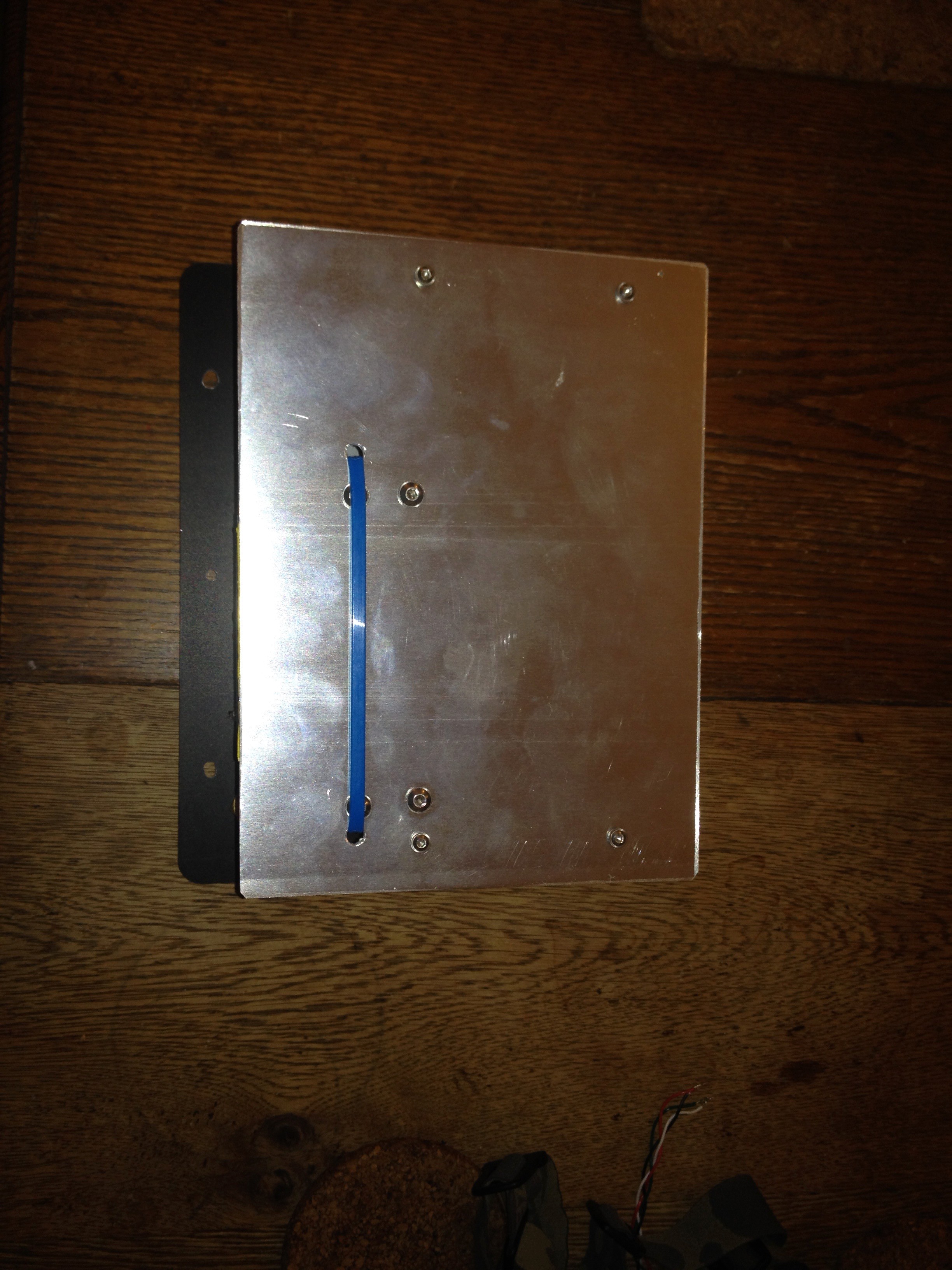
The Raspberry Pi 4 is in a heatsink case. This had to have the bolt holes drilled right through, so long bolts can go through the power hat, spacers, heatsink top, Pi, heatsink base and then hold into the back of the screen.
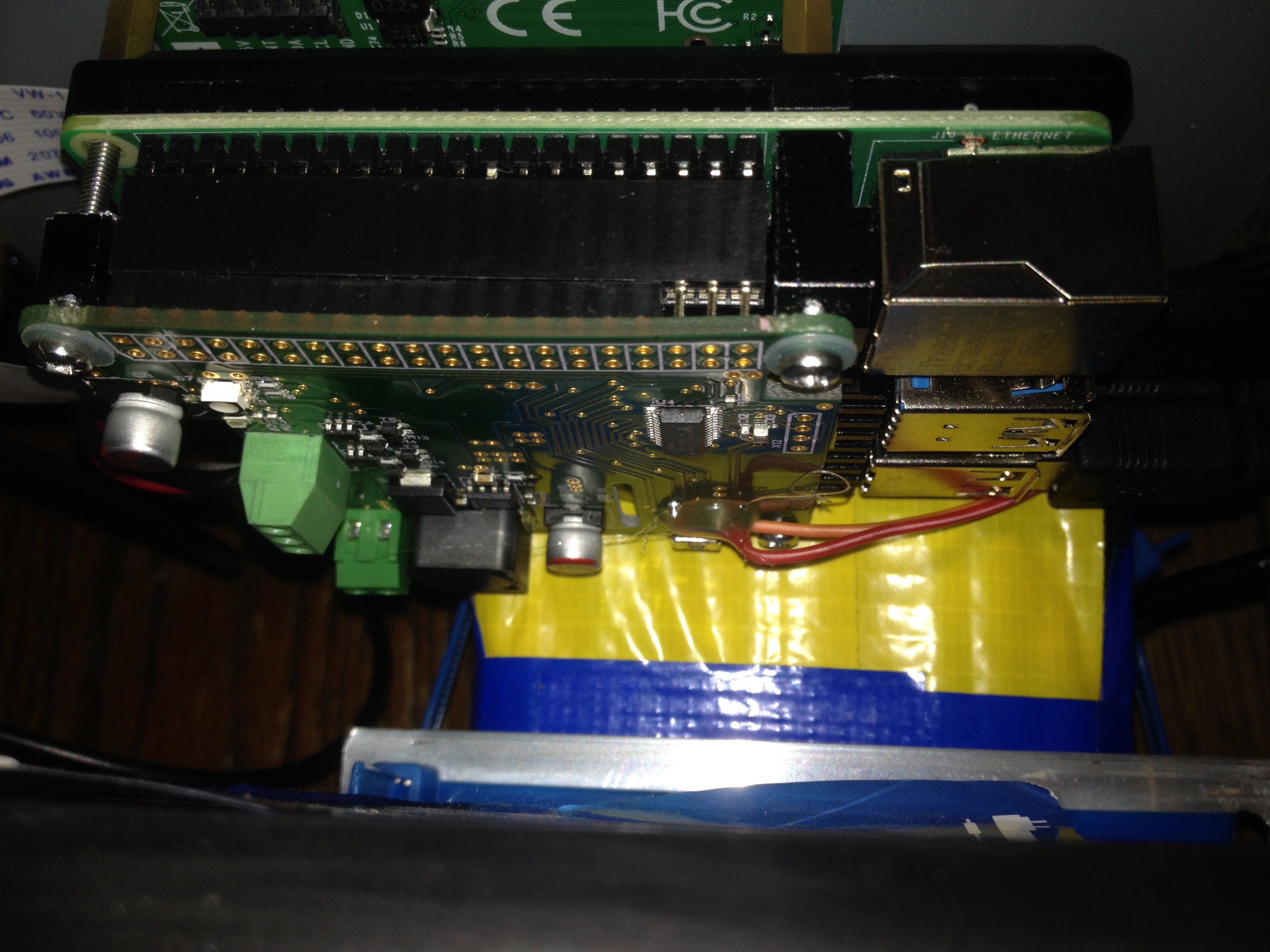
NB the heatsink is incredibly tough! I snapped a drill (Look carefully, I had to cut one corner off!) and had to end up using a carbide drill in a drill press. Not Dremel friendly! So now the hardware stack is attached to the back of the screen, with the MoPi2 power hat on the top.
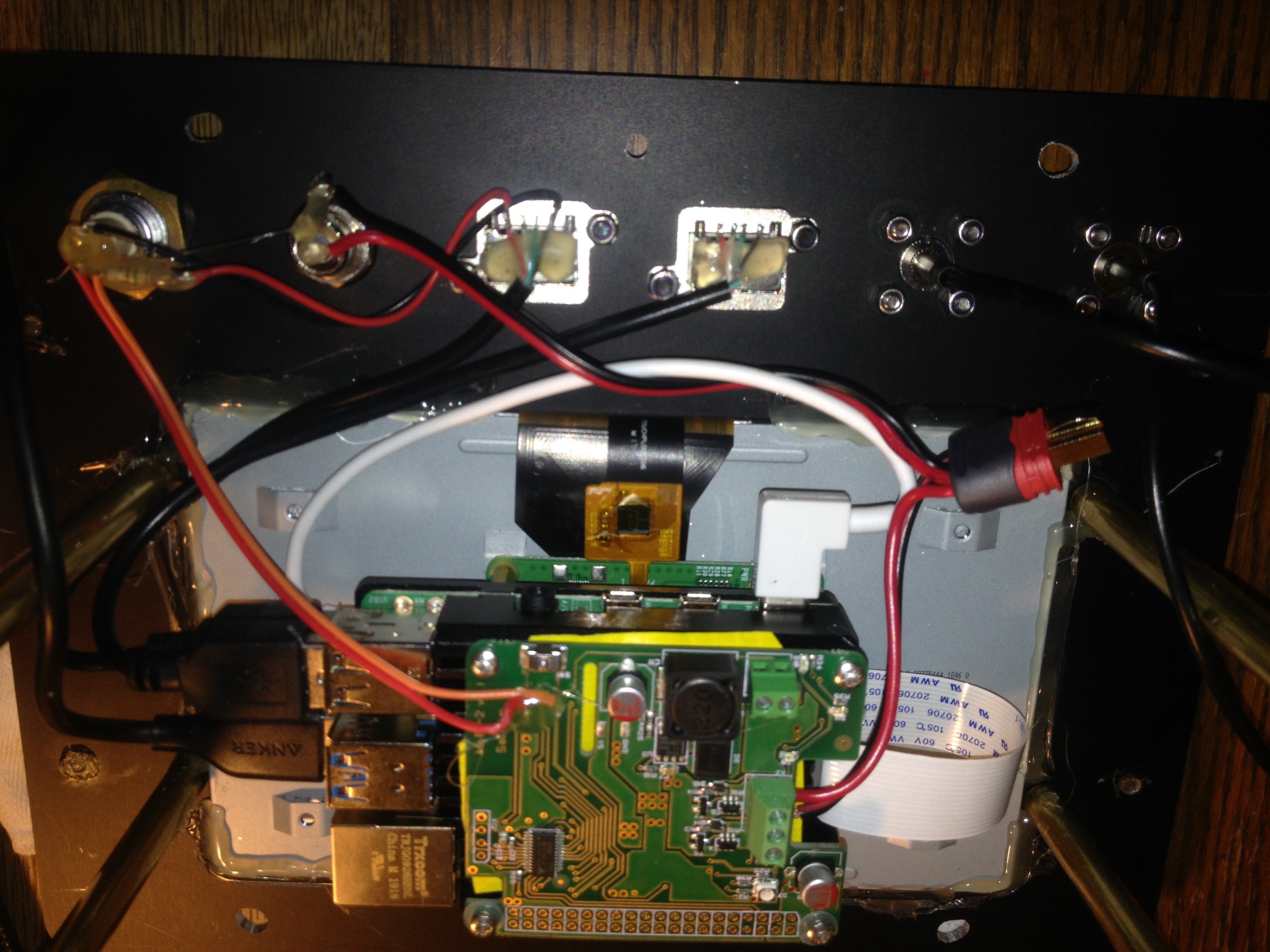
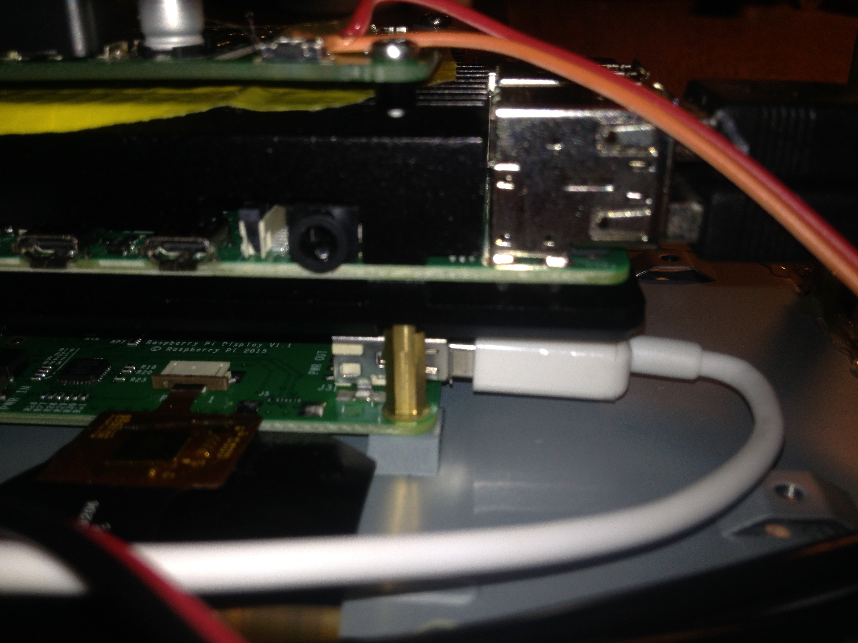
The power switch is connected to the MoPi2 EXT.SW pads and covered with a dab of glue for protection. The switch's led goes to the 5V line of the USB socket, and the USB sockets got short pigtail leads connected, and then just plugged to the Pi. The Pi hasn't had anything soldered to it: the MoPi2 hat just the power switch.
The battery is a 4P3S LiPo pack, for 4*2800mAH at about 11V with a RC-style socket. The matching plug is connected to the input of the MoPi2 and the front panel 5.5x2.1 socket, for a direct connection to the battery pack, mostly for charging. The pack is held the the back metal panel by a cable tie through a couple of holes.
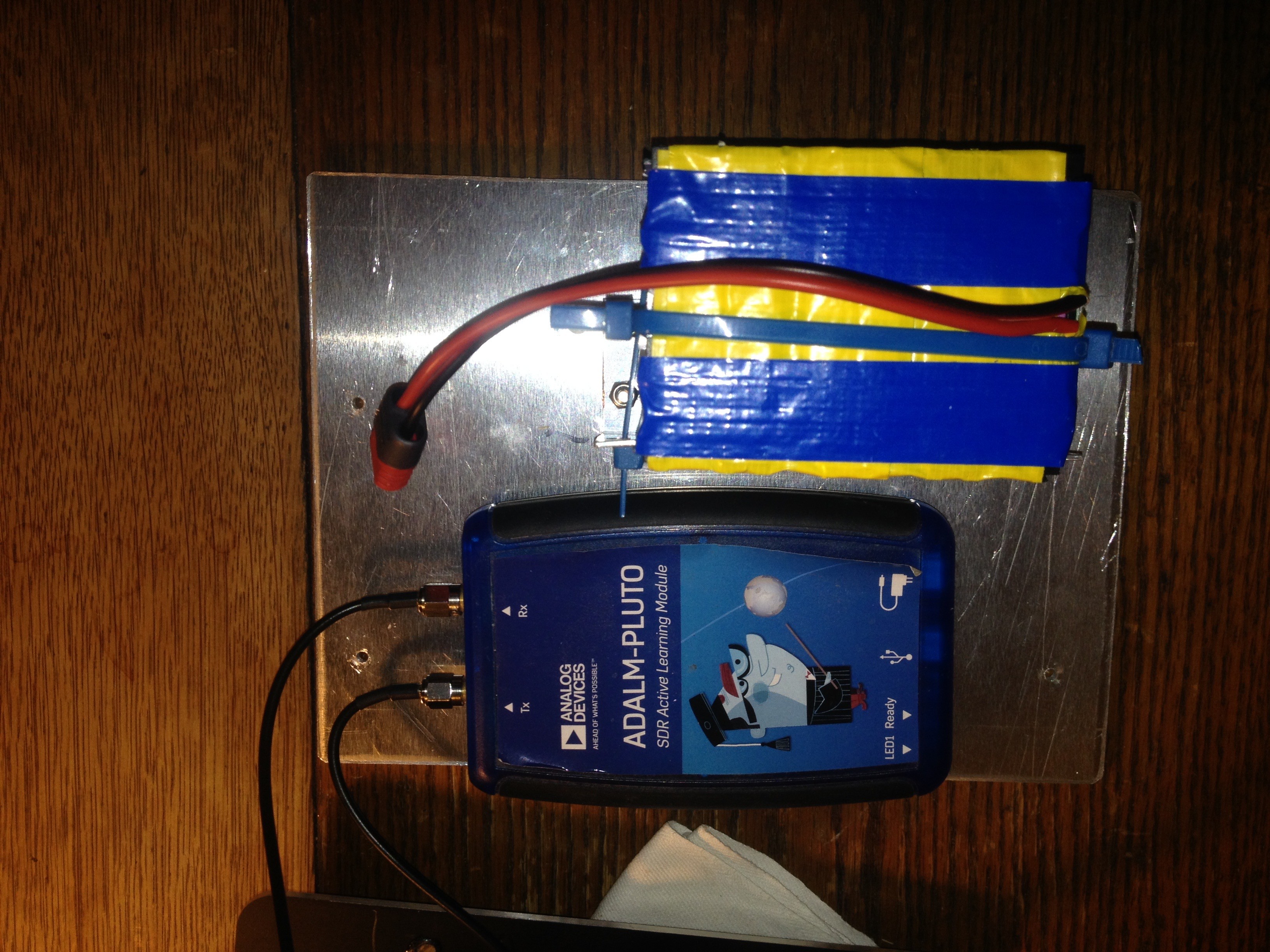
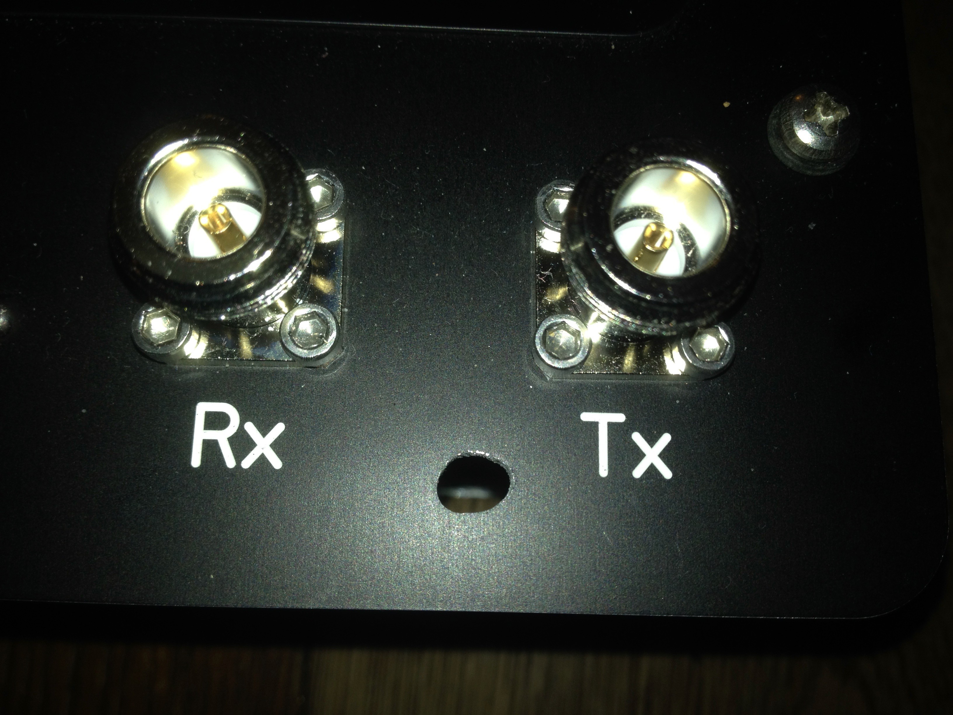
The final, radioham bit is the SDR. Either an AdalmPluto or a HackRF. This is held to the back panel by sticky pads, and is connected to the Pi by short USB lead and the front panel N-types by RG174 SMA pigtail leads.
The MoPi2 has software to report the battery voltage, but this needed...
Read more »
 Dan (a8ksh4)
 Curtis Soldano
 Raphael