Close
0%
0%

DIY Power for all - OwnTech

A fully open-source digital power electronics technology framework for fast prototyping switch-mode power supplies

Public Chat
Similar projects worth following
A comprehensive hardware and software framework to control electrical power flows !

BIG GOAL !

What if us, makers could access a true tool to electrify the world ? For Automation, mobility, power, energy storage and much more ?
What if we could gather as a whole to stand for a more sustainable electric based future built with a generic open source framework ?

We’ve seen the emergence of fast prototyping solutions for coding, we lived the booming of 3D printed, we will build the era of DIY power together !

Wait what ? Is that even possible ? Well, lets try and see what happens !

We all know the cheap power blocks we can buy for cheap from overseas, and we also know that they often do not suffice. We also know the myriad of offers of highly specialized IC’s available out there to build up a power supply from scratch with a whole bunch of knowledge involved.

But what if we could use a micro-controller to do it instead ? This way we could do software defined switched mode power supplies !

That's easier said than done because the power stage is a heck of a nightmare to design, while most readily available dev’ kits are not really good for generating super fast PWMs and sensing super fast signals while keeping their head above the water with the time critical fast calculation and the communication with the outer world.

It gets even more complicated when the power demand increases. Making beefy converters is even harder!

Going Modular !

So why not assembling a bunch of smaller (and easier to make) converters together to deliver a higher power?

Modular power
We wanted modular power

Going Versatile !

Last, most power blocks cover a specific case, which makes it less attractive as a community project. We dreamed of a generic power stage that could address most use cases out there, to make it less prone to get dumped in the dusty corner of the workshop when it is not relevant any more and also to be able to foster a community of users and makers around it.

Functional versatility
We wanted a power converter capable of achieving multiple functions


With this BIG GOAL in mind, we decided that we were eager to give this wild card challenge a shot. We’ve came with a dual solution:

  • On one hand we’ve developed a “small brain”, a specialized microcontroller dev' board with a special embedded software framework for power applications
  • On the second hand, we’ve developed a “muscle board” that is a generic power stage that can cover plenty of use cases.

And we are about to unveil it ***epic drum sound***
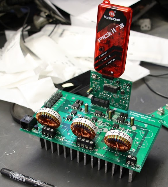
 

SPIN

Let me introduce you SPIN, the first dev’ board specialized for handling power applications.

SPIN Board photograph
The very first SPIN V0.9 board prototype

Spin do you want to say a word about yourself ?

Hello World !  

Brilliant! It even speaks !

And here are its perks :

  • It is thought to be the power brain of your future project
  • It has a small form factor and you can solder it onboard of your very own power stage
  • It has a super special framework that we’ve developed to get on track super fast and deploy super precise PWMs, super fast measurements all of that with simple ergonomics

From the software perspective, we have written the OwnTech Power API code. Based on the ZephyrOS, an open-source RTOS driven by the Linux Foundation, our code is a driver to low-level peripherals that are essential to the control of power hardware. By using this approach, our code is vendor agnostic, which opens the door to supporting more vendors and aggregating a larger community on the long term. In practice, this means improved software resilience. Our code is fully compatible with PlatformIO and can be easily downloaded, compiled and flashed using VSCode.

To be able to talk and monitor SPIN, we have written a data-monitoring tool called OwnPlot. This serial based data acquisition system allows the users to monitor any data being sent via any serial port to a target computer. This platform-agnostic application allows data logging and will, on the longer term, provide a GUI...

Read more »

Definition_Package_TWIST_Board.zip

Inside are the Gerbers for TWIST together with an interactive placement HTML file to build the board

Zip Archive - 1.71 MB - 10/04/2022 at 16:50

Download

Definition_Package_MCUSPIN.zip

Inside are the Gerbers for SPIN together with an interactive placement HTML file to build the board

Zip Archive - 402.55 kB - 09/30/2022 at 10:00

Download

stencil.zip

Gerber to order a stencil for both TWIST and SPIN

Zip Archive - 9.68 kB - 09/30/2022 at 10:01

Download

  • 1 × Computer !
  • 1 × 1 STLINK V3
  • 1 × BOM SPIN provided
  • 1 × BOM TWIST provided
  • 1 × PCB SPIN

View all 6 components

  • Making the doc available

    Luiz Villa10/09/2022 at 13:29 0 comments

     Documentation is the beacon that lights the path of an open source project. As such is should be visible and easy to find. But have you ever tried to actually build the documentation? That is exactly what I tasked myself to do and this is my journey.

    I have started thinking of the high level requirements : what would be a good way of documenting the project as a whole ?

    Requirements :

    • Everyone should be able to edit the documentation and propose a pull request to improve it
    • The documentation should be kept close to the content so that each repo have easy to find explanations
    • Being able to parse the markdown content of our multiple repositories in one single place on the internet as a Static website. 
    • Publish these files at docs.owntech.org

    First things first: aggregating content

    We use the wikis integrated into our gitlab forge as a means to document our work. It has several advantages, such as support for some specific markdown perks (more details here).

    Building on the work from Guillaume and Jean, I aggregated the content that explains the hardware for both spin and twist in their respective gitlab wikis.

    The SPIN and TWIST wikis at gitlab
    A view of the SPIN and TWIST wikis at gitlab

    Once the content is aggregate comes the question: how can people find it?  

    How to spread the word: finding parsing methods for the content

    Having the documentation in markdown is a great advantage: there are many ways to parse it and make it available online. However, there is also a great challenge: markdown flavors are a dime a dozen.

    Choosing a parsing method requires supporting the chosen markdown flavor and automatically deploying it a website. The strategy was two-fold:

    • Automatic wiki generation: by using git submodules we could aggregate all wikis in a single git, which we could then use either to manage them or automate their deployment
    • Keeping editing simple: by using the editing interface of gitlab, we wanted the community to still be capable of engaging and correcting the documentation without learning the elfic ways of markdown.

    We will simplify our story and give you our two latest attempts to reach this goal.

    The Docsify attempt

    When we came across docsify we though that it would be a great tool for automatically parsing our wikis.

    OwnDocs docsify landing page
    The docsify landing page - Full of promise!

    However, like all other methods, it does not support gitlab flavored markdown. We though it would still be worth the trouble and went on with the idea that we could adapt our work just enough to use it well.

    And so we did. Wiki by wiki we took the pain to correctly verify that evything could parse and show up nicely on our docsify instance.

    Markdown in three different formats and not parsing in docsify
    The markdown house of cards

    And after everything was said and done, we were ready to deploy!

    The server incident

    Here we were happy to achieve a great documentation which we were ready to transform into HTML and deploy. But that feature is not supported by Docsify. And our server service provider does not allow us to deploy anything but static HTML pages to our website.

    We find this out, of course, on october 9th, a few hours before the hackaday deadline.

    So, what now?

    Docsaurus as a solution

    Armed with a greater resolve and shorter time, here we found ourselves asking what solution can we deploy that will take all of our work AND render a static HTLM page?

    After hunting for clues online, we came across Docusaurus.

    Docsaurus let's go!
    Getting started at 3AM? Yes, sure, what could go wrong?

    Docusaurus was a very pleasant surprise! Easy to understand, it was a short stretch from the work we did with docsify, giving us an automatic sidebar and the means of getting as much information from the SPIN and TWIST wikis as possible with no re-work.

    OwnDocs finally online!
    The online version of OwnDocs

    You can now find the first version of our hardware documentation aggregated on our website: docs.owntech.org  

    Happy reading!

  • Pinouts and doc

    guigur10/09/2022 at 01:27 0 comments

    A quick presentation.

    A good project is NOTHING without good and understandable documentation. I've always loved good pinouts of dev boards, I think they save so much time and effort that they are a necessity.

    I've searched a bit online and found PCBDraw by Jan Mrázek (https://github.com/yaqwsx/PcbDraw). It's a fantastic tool from which you can convert your KiCAD PCB to a Vectorial image. 

    Happy and full of myself with my nice SVG image, I then search for a good pinout maker software, and no dice. Such projects do exist but didn't fulfill my needs. 

    Some (too much) coffee later, I made a little program in Python that does just that!

    The program takes a JSON file describing all the functions of all the pins you want to document and generates a nice SVG image. My code is quite messy and not well documented (ironic ?) but it was made specifically to meet the deadline of the Hackaday wildcard challenge. 

    What 3 nights of not enough sleep gets you? 

    I'm glad you asked, this is our dev board SPIN!

    SPIN Pinout
    SPIN Pinout

    Be aware that some assembly is required. The current version of this program only generates the "pins" and the legend. All the images, text, license, and adjustments are made after the fact on Inkscape!

    So what this piece of kit does deliver?

    This is a sample output file untouched straight from the program:

    Raw unfiltered SPIN Pinout
    Raw unfiltered SPIN Pinout

    Pretty neat hun? I like to think this is pretty similar to buying a piece of Swedish furniture and putting it together yourself. Jokes aside, a later version of the software could take care of a lot of messing around but I need some rest.

    How do I feed this monster?

    Each pin is made of labels, and each label has a style and may have categories.

    Buckle up it's going to be quite the ride from now.

    A style.json file describes all the available styles present in your pinout. They define the color of the label as such as the skewed factor and special capabilities (hidden label, dummy label, only text label).

    The legend plot the label in the same order as they are described in the style.json.

    A sample of the styles of labels in styles.json
    A sample of the styles of labels in styles.json

    And for the pins themselves, we define the side (the orientation Left to right or Right to left), PWM capabilities, and most importantly the functions.

    Each function is a label but is not necessarily plotted in the final image. We have to enter each name of the label in the name field, each style corresponding with a style in style.json, and so forth.

    And finally, the categories able you to filter and omit categories of pins to simplify your pinout without redoing this file each time you change your mind (trust me it's a real-time saver).

    Sample of spin_pins_L.json
    Sample of spin_pins_L.json

    Without this feature, our SPIN board would flood like this monster! And the last thing I want from a doc is to get a headache.

    Way too much information for me
    Way too much information for me

    How about TWIST?


    TWIST is a similar story to SPIN, with this tool I was able to generate labels and a nice-looking pinout cheat sheet. I like to cut away pieces of the board SVG on Inkscape to enhance visibility. 
    TWIST Pinout
    TWIST Pinout

    What's the name of this amazing life-changing tool?


    I may have some talent for programming and electronics but finding a good name is not one of my forte. I was not able to think of a better name thank PinMaker...
    So If you want to poke around my code and give me some advice, you can find the sources here https://github.com/owntech-foundation/PinMaker
    Keep in mind, this is still pretty unfinished and I hope to polish the project in the near future.
    Happy pin-making!
    (I really need to think of a better name for my next project)

  • Incremental Hardware improvements - The Monster Museum

    Jean Alinei10/05/2022 at 17:12 0 comments

    Hardware is Hard !

    We wanted to give a quick summary of our different preliminary prototypes and their weak points so that it might be useful to someone !

    When you design a project you always want it to be simple to debug and to be quite robust so that it meets the initial objective. Our thoughts were rather to make a product that can be assembled and maintained easily rather than to make it super robust and integrated from scratch. As such, we wanted to test out the design function by function, and assembling them as lego blocks.

    We also wanted to comply with as many "standards" as possible - usually mechanical parts tend to account as big expenses in the final BOM - Especially when you have designed your board with funny dimensions, and you need a non standard heatsink or casing.  So we naturally decided to limit ourself to the 100mmx100mm that became quite popular because of PCB manufacturers special offers - while still possibly comply with the 19" racking system standard sizes. (3U format is 100mm tall). We tolerated to increase the PCB surface up to 160mmx100mm to match with the EuroCard format.

    #1 An attempt at using PCI standard to get cheap connectors

    This is a really old attempt but it is still worth documenting as it turned out pretty well - We used a 36 contacts PCI connector to tie a micro controller board to the power stage. This was really cheap, as we only had to pay for one standard connector to get 36 contacts.

    The big downside is that it is not low profile at all, and the size of the micro controller board will give the final height of the product which can ends up adding a lot of cost to the casing.

    Second downside here is that you need to concentrate all the signals to the same spot on the design so you quickly end up  mixing analog signals and digital signals at the same location which is not good practice. 


    #2 An attempt at building a vertically integrated prototype with headers

    This prototype had no name, and was built with 4 different pcbs stacked on each other with headers.

    • The power PCB with the switches, power inductors and capacitors and current measurements
    • The driver stage with the mosfet drivers
    • The measurement stage with the voltage measurements and the feeding system.
    • The micro-controller board that was a nucleo board back then.
    Modular first prototype
    Modular first prototype
    Side view
    Side view


    The obvious big drawback of the design was the headers.

    These things appear to be a good candidate at first glance, but stacking pcbs with headers revealed itself to be a poor choice. The pins were indexing the mechanical assembly and it was producing quite a lot of constraints on the assembly.
    Headers are never perfectly aligned and they bend at each disconnection, they so they quickly wear out.


     #3 An attempt at making a back to back prototype with pogo pins

    On the next prototype we've used pogo pins instead that were providing an electrical contact without constraining the mechanical assembly. It yielded far better results. Two PCBs were mounted back to back - One PCB was the power board, while the second one was the micro-controller board. The stack was screwed together with a 3D printed spacer in between. The low profile spring loaded pogo pins were ensuring the electrical connections.


    O2 second version
    O2 second version

    O2 microcontroller side

    Microcontroller side

    This new mechanical architecture was far more robust - but it had one severe drawback : thermal properties. The surface mounted transistors had to be cooled from the top which is unconventional. In fact, the most effective way of cooling SMD transistors is to pipe the heat through thermal vias through the pcb and evacuate it from the bottom side. Trying to do differently was not a great idea, the heat had to be piped through the thin layer of top copper (35µm thick) which offered poor thermal performances. (Yes the image is saying the opposite, but no, it was not at all efficient heat sinking).

    The second severe drawback was cost. Each contact...

    Read more »

  • Why open-source power electronics? - Manifesto -

    Jean Alinei10/05/2022 at 15:52 0 comments

    As we studied the problem we realized that energy access was not an exception. Everywhere we turned people needed to electrify something and were struggling with power electronics technology access. Prototyping motor control, battery charging or simply powering a lab was always done via a black box that no one can understand or repair.


    Education

    In the case of power electronics, the issue of technology access is multidisciplinary. Power engineers need to understand power switches, classic electronics, EMI, EMCs, thermal dissipation, filters, control theory, software design, industrial informatics and IoT. The sheer amount of knowledge necessary to properly create a power converter is mind blowing. 

    This intrinsic complexity push teachers to teach it through theory rather than from practice. Yet we think that learning by doing is thousands times better as it develops know-how together with the great feeling of being useful for a greater cause.

    In the meanwhile, society is rushing out shift away from fossils and is turning toward de-carbonized electricity as tomorrows main energy supply. That implies massive numbers of highly trained personnel to take up the challenge. Thus - we need an affordable educational tool to learn power electronics by doing -

    Open Innovation

    Everywhere we turned people needed to electrify something and were struggling with power electronics.  Prototyping motor control, battery charging or simply powering a lab was always done via a black box that no one can understand or repair. As such, we learned that technology and knowledge access is as important as the energy access. And since that we firmly believe that fighting the black box effect will permit the emergence of spontaneous grassroots innovation in various fields such as:

    • Mobility
    • Renewables
    • Energy storage
    • Micro-grids
    • Automation

    Toward a global movement ?

    Lets stand together to create a decentralized open knowledge center ! Lets create joints device that will cover local needs and fight back the black box effect. From this open framework, us engineers will have the capabilities to think solutions that can be

    • Understood
    • Repaired
    • Maintained
    • Improved
    • Hacked

    A light in the night
    A light in the night

  • Why one more API ?

    Jean Alinei10/04/2022 at 17:44 0 comments

    There are so many APIs already, why should we develop a new one ?

    To us, the key of democratizing access to this world crucial technology is to make it simple to understand and simple to hack !

    Breaking down the complexity barrier implies :

    • Simple ergonomics
      • No complex installation process 
      • Having a graphical interface
    • Adapting to existing practices
      • Some people working on the field to use C to program
      • Most people use vendors API to address registers
      • Some users are familiar with real time OS such as FreeRTOS
      • Other develop algorithm on Matlab

    We found out that adapting to different practices while ensuring great ergonomics is really hard. Below is a bit of history of what we've tried !

    #1 Attempt as using Arduino to make power converters

    We always wanted to have an Arduino like example for our power converters. So, of course, we first tried using arduinos for our power boards.

    Deprecated prototype
    An old prototype that was embarking an Arduino Nano


    It appeared that Arduino was having quite some trouble with fast PWM and signals measurement.
    The resolution of the signal was low, while the ADC were imprecise. Altogether it was kinda working but the program itself became quite complex to develop with not so intuitive calls to ATMEL registers.

    Our return of experience was that Arduino board and API were unable to

    •  To configure the peripherals to generate all kind of PWM that could be useful for power conversion and synchronizing measurements without using precious processor time.
    •  To be able to deploy complex control algorithm at a time critical pace. Without spending a TON of time in the search of reducing the computational effort.

    The pros were :

    • It was a cheap
    • The Arduino IDE is super easy to install and well documented
    • It was open source friendly

    #2 Attempt at using a 16 bit DSP together with Matlab code generation

    We also wanted to try using a quite cheap yet plenty powerful 16bit DSP to compare it with the Arduino attempt, and also tried to generate the code directly using a Matlab Simulink blockset. We ended up choosing the dsPIC33EP256MC202.

    dsPIC33EP256MC202
    The small PCI based dsPIC33EP256MC202 dev' board

    The board was definitely better at generating PWMs and adressing the measurement challenges, but understanding its register was tough. We were mostly relying on the vendor APIs and tools.

    The toolchain was not so easy to install, and we were kinda tied to use the vendor IDE as well. The 16bit DSP was hard to master, as most of the fast computation were relying on understanding fixed point calculation. - I still do nightmares at night about it -

    We choosed this chip for its capabilities, but also because it was supporting code generation from Matlab Simulink. We thought it could be cool to try it out.


    Matlab block screen capture

    Matlab block screen capture

    The block-set was well thought, dedicated blocks permitted to control the dsPIC peripherals. Yet, some functionality were missing and back then it was quite buggy. We took ages to find the workarounds for  "simple" things that were not working properly. Moreover, the Matlab ecosystem support was a great feature, but could not cover the users who were used to C code programming with a simple ergonomics.

    The last thing that was making us unhappy is that we were kinda tied to proprietary and vendor specific solutions to develop our software which was prone to obsolescence and not really compatible with the BIG GOAL of gathering a vibrant community.

    Our return of experience was that the dsPIC board and the Matlab Simulink were unable to

    • Provide simple - bug free - ergonomics for begginers.
    • Provide an open source friendly pathway
    • It was lacking Floating Point Unit (FPU) support

    The pros were :

    • It was a cheap chip
    • It was fast
    • The Matlab support was still a really nice feature

    That's why we started this journey of developing our own intuitive API for power conversion.

View all 5 project logs

  • 1
    Download the gerber files attached

    Get your fresh copy of SPIN and TWIST gerbers.

  • 2
    Send the gerbers to your favorite PCB manufacturer

    You might want to order a stencil as well to reflow the components instead of soldering them one by one.

  • 3
    Order the BOM

    All the components references are available in the interactive BOM inside of the definition package.

    Find the html file provided
    Find the html file provided to order the BOM


    The column Manf# provide the unique reference for each component.
    Pro tip : #manf is thought to be compatible with KiCost plugin to source your part easily.

    Interactive BOM
    Order the BOM that is given in Manf# column

    When your components are sourced, make sure you ticked the "sourced" tickbox :D

View all 10 instructions

Enjoy this project?

Share

Discussions

Similar Projects

Does this project spark your interest?

Become a member to follow this project and never miss any updates