 Capt. Flatus O'Flaherty ☠
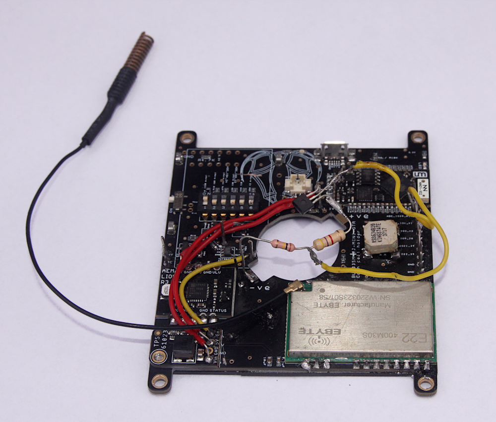
Looking carefully at the photo below, there can be seen 2 resistors and a NPN transistor floating above the main board. Form the +ve battery terminal, there is the collector of the ZTX450 transistor with a 4.7K resistor soldered to the emitter. Then, there's a 100K resistor which goes to ground. The base of the transistor is activated by one of the MCU pins on one of the yellow wires and the voltage detected via the other yellow wire to another MCU pin. 3.925V gives a reading of 2923 out of a possible range of 4095 (12 bit) so there's plenty of head room for higher voltages, for example, 4.1 volts, which seems to be the maximum charge voltage on the battery.
Thankfully, after a bit of trial and error in arriving at this configuration, no diodes were required !!!
Discussions
Become a Hackaday.io Member
Create an account to leave a comment. Already have an account? Log In.