 Ruediger F. Loeckenhoff
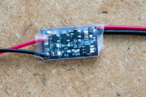
Build the circuit and connect it to the VI.direct tx cable in correct polarity, i.e. the TX port should go to +5V in comparison to GND. Use your smartphone to connect to the Victron smart solar and go to settings. Configure the TX port as virtual load output. Connect a continuity tester to the SSRs output and switch the virtual load output from "always on" to "always off". You should hear a beep from the continuity tester. It should not beep when you go from "always off" to always on.
Now try, whether this simulated pushbutton is capable of switching your inverter or whatever you want to switch.
Probably not all inverters will have this handy pusbutton port. If they don't you might consider connecting the motor of a cheap servo directly to a 5V supply which is switched by the SSR such that it pushes the button mechanically. You might need a somewhat stronger SSR such as the CPC1907B in this case. (I love this part, it is such a great problem solver).
The 5V supply could be a step down inverter.
 Christoph Tack
 Bud Bennett
 aymen
aymen