 Maksim Surguy
The build process for this project consists of the following components:
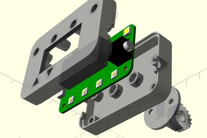
- Create a 3D printable individual 7 segment display
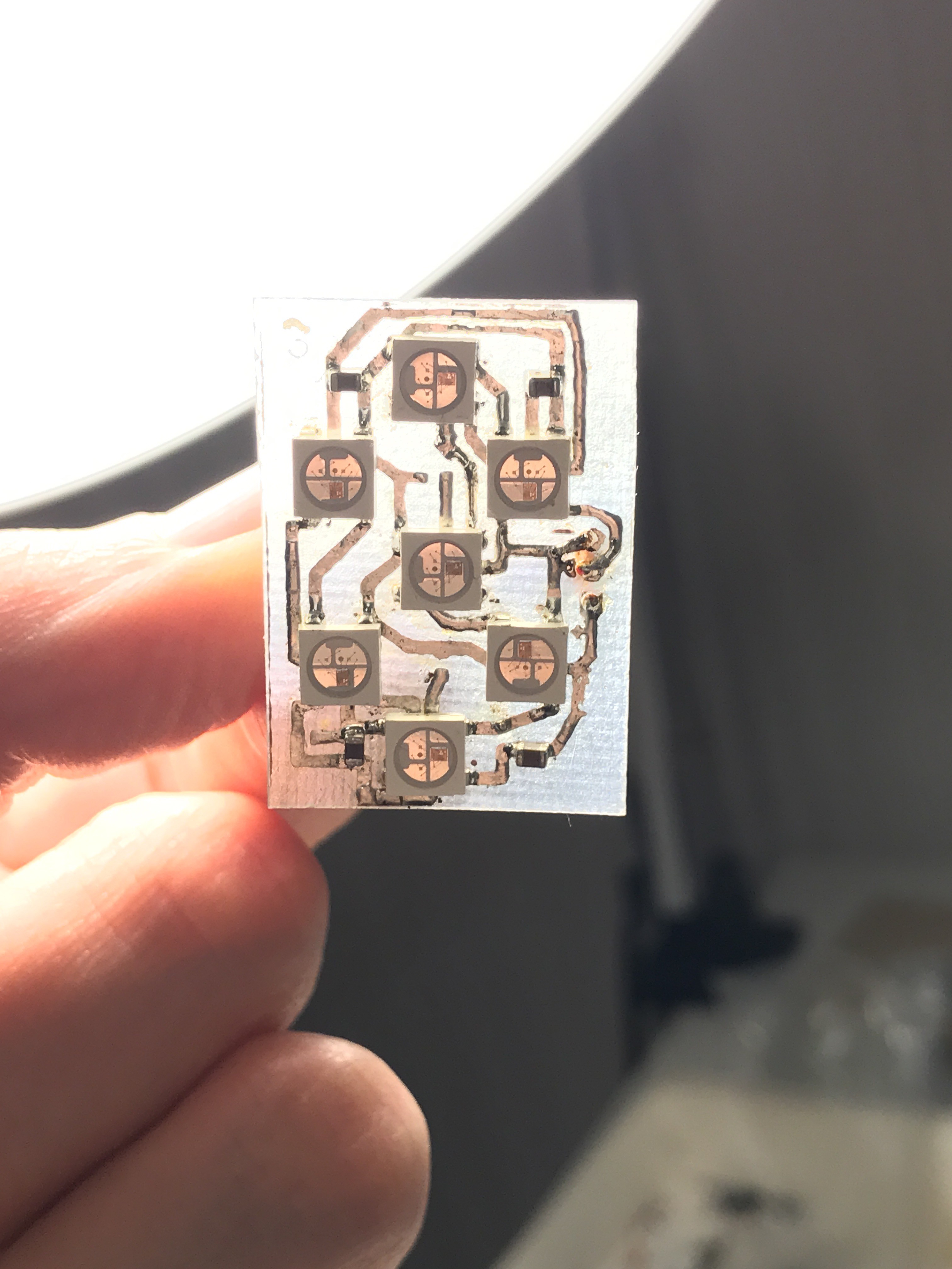
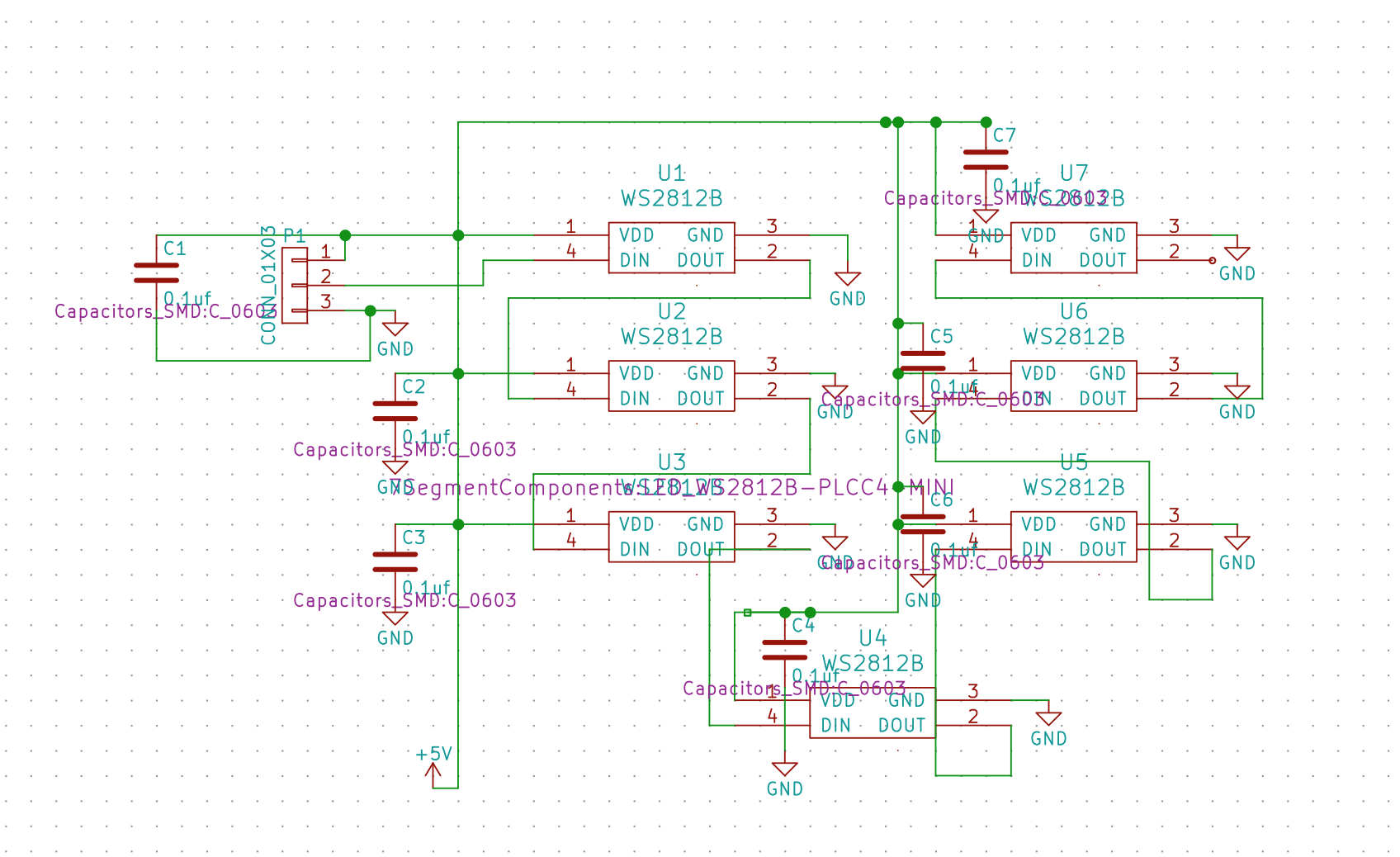
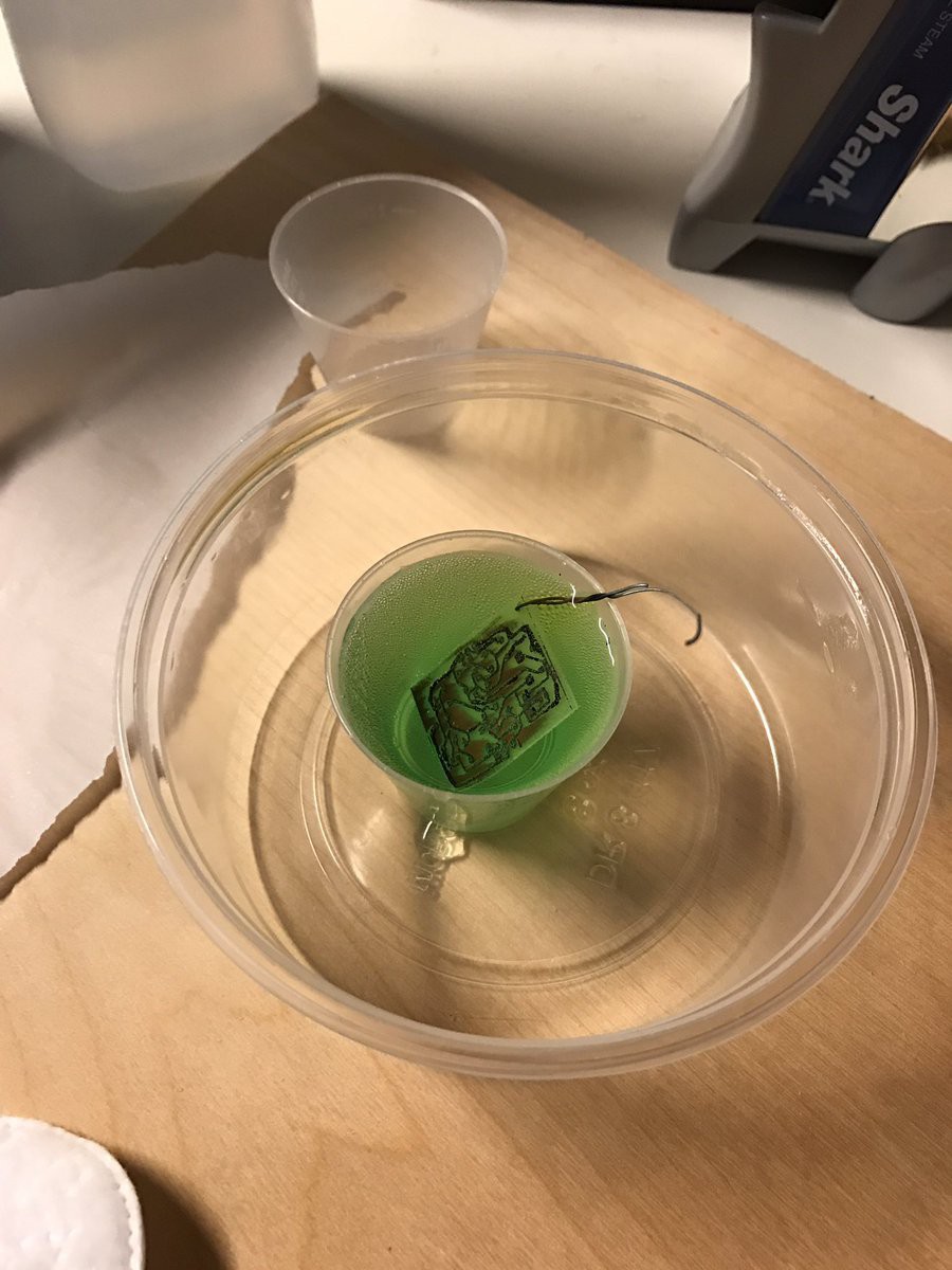
- Create schematics and PCB for individual display
- Create Arduino Library to drive some number of 7 segment displays
Here's the latest update for this project:

 SUF
SUF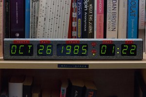
 Stephen Holdaway
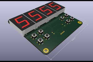
 Ken Yap
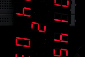
Hey, nice work! Have you seen my library? https://github.com/h-c-c/Seven_Segment_Pixel You can pull it in through the library manager in the Arduino IDE.