 Mx. Jack Nelson
Infinite stories from an AI bear
Any TJ Bearytales can be your own artificial intelligence storytelling bear with these simple* modifications.
* complicated
Reprogramming T.J. Bearytales into a helpful, empathetic robot
Already have an account? Log in.
To make the experience fit your profile, pick a username and tell us what interests you.
Any TJ Bearytales can be your own artificial intelligence storytelling bear with these simple* modifications.
* complicated
Each of TJ's motors is paired with a positional encoder. By reading these positional encoders, we can sense the position of Tj's arms, head, eyes and ears.
In this demo, we'll start by activating the motor that controls TJ's eye blinking and ear wiggling loop. Then, we will read the state of each of the two GPIO pins connected to the positional encoder associated with that motor. Finally, we'll evaluate the readings to find the position of TJ's eyes and ears.
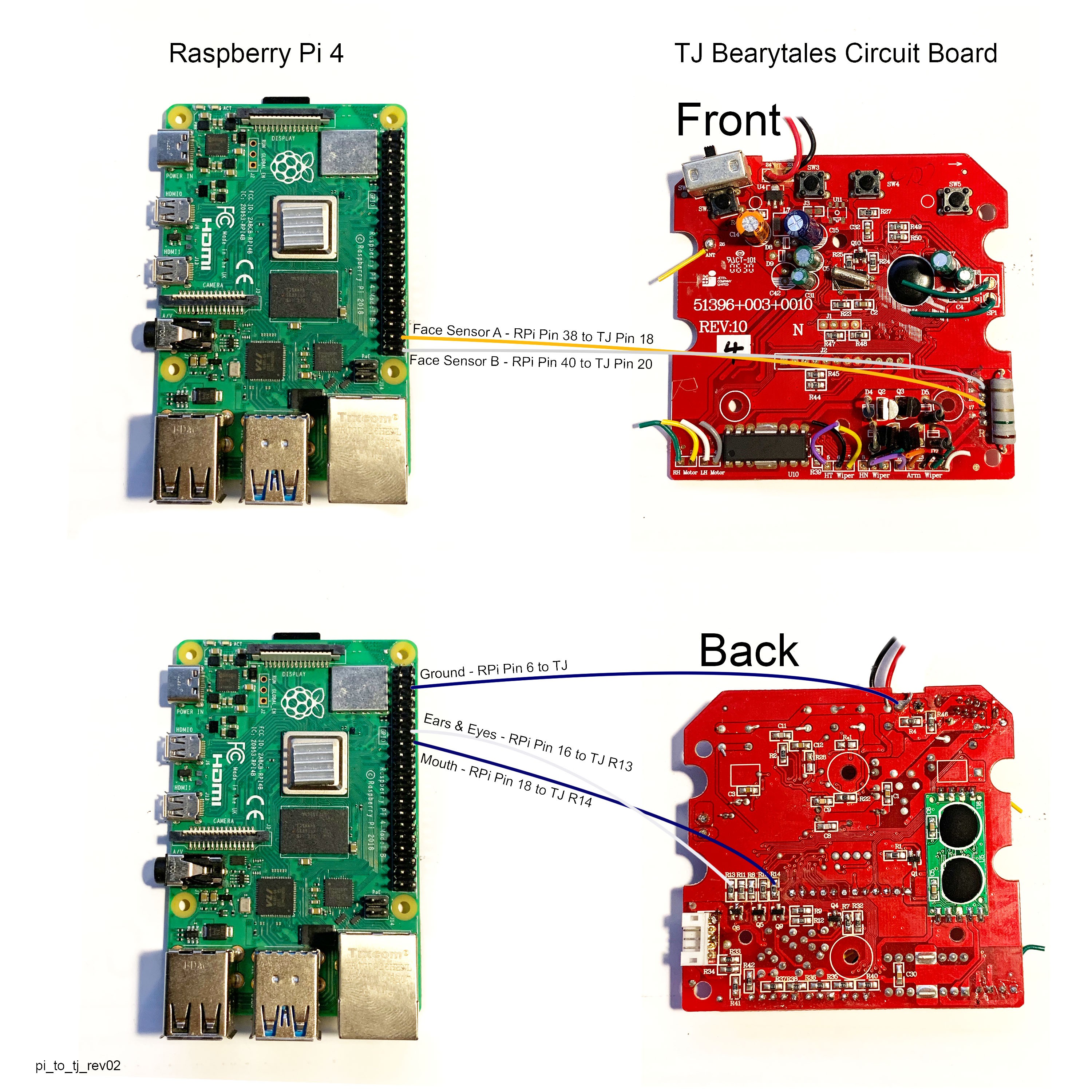
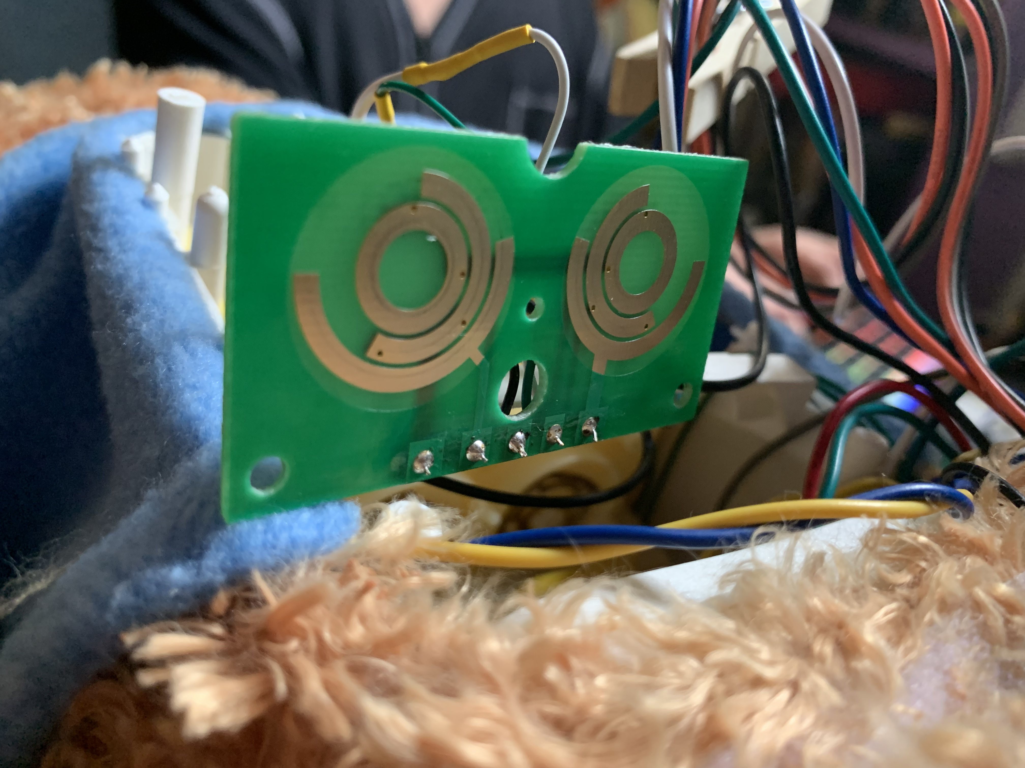
But first we needed to solder two wires to TJ's positional encoder on the front of the board. We then attached the wires to GPIO pins on the Raspberry Pi.
We wrote the following code to read the value of the positional encoder associated with TJ's eye blinking and ear wiggling loop.
#Script to test one of the positional encoders on TJ Bearytales

# Copyright 2023 Steph & Jack Nelson
# SPDX-License-Identifier: MIT
# https://hackaday.io/project/187602-tj-bearytales-rewritten

#Import libraries
import time
import RPi.GPIO as GPIO

# Set the GPIO numbering mode to BOARD
GPIO.setmode(GPIO.BOARD)

# MotorC:
earsEyes = 16
mouth = 18

# Set up the GPIO pins for the sensors
# Face Sensors
faceSensorA = 38
faceSensorB = 40

# Setup all pins we are using to control motors as outputs and set them to low
for motorPin in [earsEyes, mouth]:
    GPIO.setup(motorPin, GPIO.OUT)
    GPIO.output(motorPin, GPIO.LOW)

# Setup all pins we are using to read sensors as inputs and set them to be pulled up
for sensorPin in [faceSensorA, faceSensorB]:
    GPIO.setup(sensorPin, GPIO.IN, GPIO.PUD_UP)

try:
    GPIO.output(earsEyes, GPIO.HIGH)
    while True:
        # Read the state of the GPIO pins
        pinStateA = GPIO.input(faceSensorA)
        pinStateB = GPIO.input(faceSensorB)
        if pinStateA == True and pinStateB == False:
            status = 'Eyes Opening'
        if pinStateA == True and pinStateB == True:
            status = 'Eyes Open, Ears Wiggling'
        if pinStateA == False and pinStateB == True:
            status = 'Eyes Closing'
        if pinStateA == False and pinStateB == False:
            status = 'Eyes Shut, Ears Still'
        print(f'SensorA: {bool(pinStateA)} \tsensorB: {bool(pinStateB)}  \tPosition:{status}                        ', end='\r', flush=True)
        time.sleep(.01)

except:
    # Ensure all motors are off
    for motorPin in [earsEyes, mouth]:
        GPIO.setup(motorPin, GPIO.LOW)

    # Clean up GPIO resources
    GPIO.cleanup()
    print('Cleanup Done.\n\n~~Thanks for playing!~~')
In this video you can see the test running, and in slow motion you can see the different states of TJ's eyes and ears, and the value reported by the positional encoder.
The results of the test are that the eyes open motion state corresponds to the 'true true' positional encoder state, and that the eyes closed motion state corresponds to the 'false false' positional encoder state. You can see that these pins have not been debounced, and so the results are somewhat noisy. You can write this test for all of the three sensor pairs to evaluate which positions correspond to which encoder states.
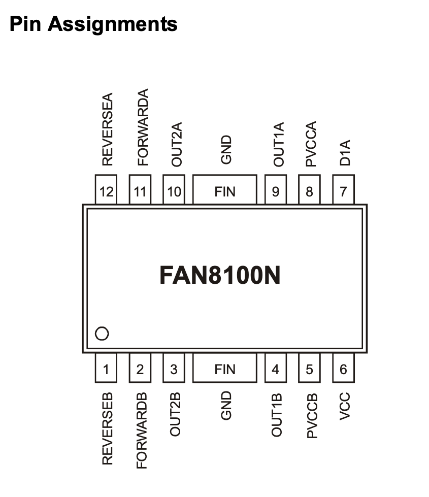
TJ Bearytales has three motor controllers located on his board. The pin assignments for the motor driver tell us that the top two left pins 12 and 11 are ReverseA and ForwardA, and that the bottom two left pins 1 and 2 are ReverseB and ForwardB. Before attaching wires to the pins and resistors we tested his movements with a jumper wire.
Attaching wires to the correct points for each of TJs motor controllers is shown below.
The three motors are controlled by the following pins in this configuration.
We took our newly installed wires and connected them to the GPIO pins on the Raspberry Pi, including a ground wire from TJs board to a ground pin on the Raspberry Pi. 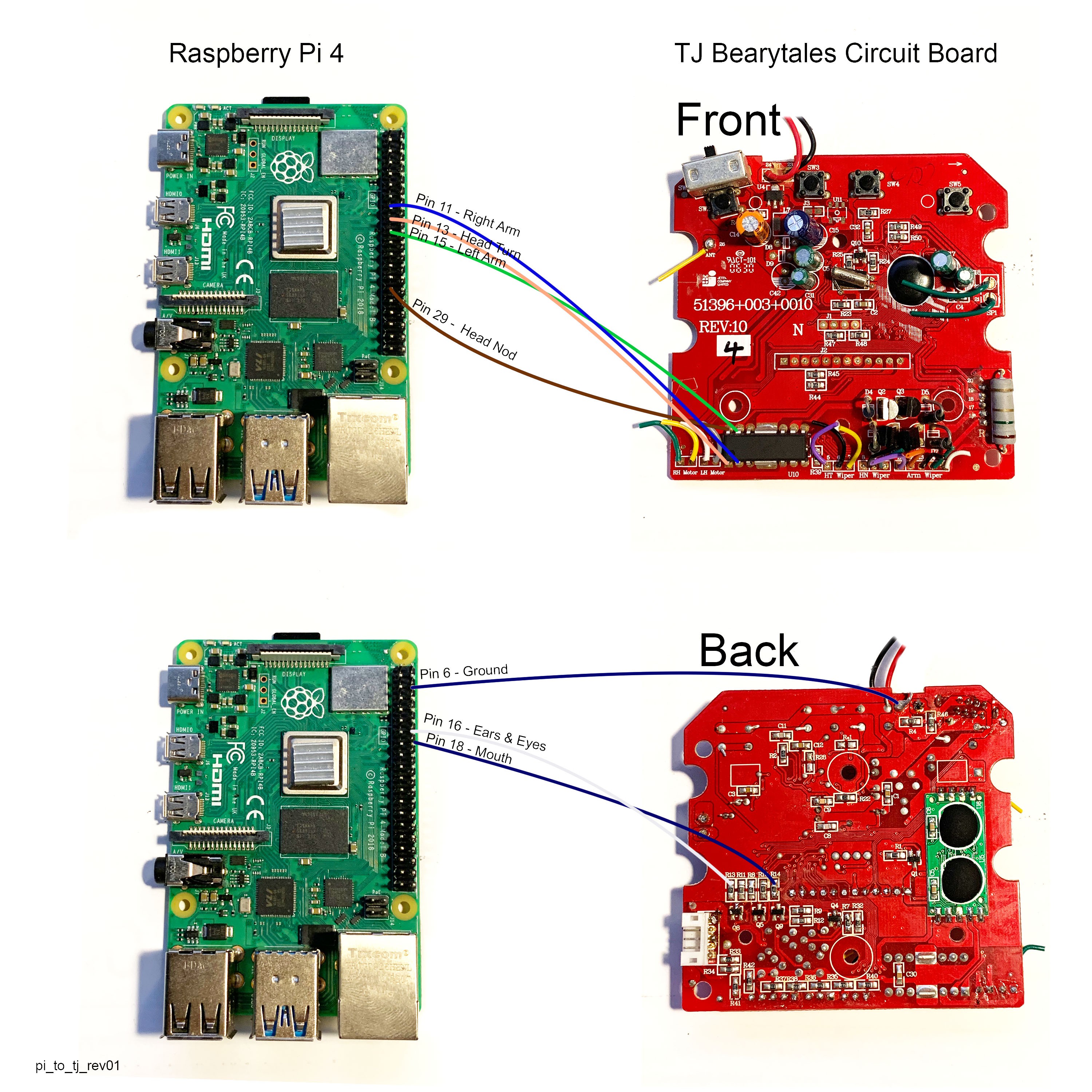
We used the following code to define which GPIO pins are attached to which motor controller, and then control them.
#Script to test all three motors of TJ Bearytales

# Copyright 2023 Steph & Jack Nelson
# SPDX-License-Identifier: MIT
# https://hackaday.io/project/187602-tj-bearytales-rewritten

#Import libraries
import RPi.GPIO as GPIO
import time

# Set the GPIO numbering mode to BOARD
GPIO.setmode(GPIO.BOARD)

# Define which GPIO pins are attached to each motor control input,
#     two pins per motor, one for each direction. Diagram in link.
#MotorA
rightArm = 11
headTurn = 13
#MotorB:
leftArm = 15
headNod = 29
#MotorC:
earsEyes = 16
mouth = 18

# Setup all pins as outputs and set them to low
for motorPin in [rightArm, headTurn, leftArm, headNod, earsEyes, mouth]:
    GPIO.setup(motorPin, GPIO.OUT)
    GPIO.output(motorPin, GPIO.LOW)

# Setup a function to start the motor, pause, then stop the motor
def Motion(motor, duration):
    if motor == mouth and duration > .25:
        duration = .25 #always force this short duration to prevent jamming mouth open
    GPIO.output(motor, GPIO.HIGH)
    time.sleep(duration)
    GPIO.output(motor, GPIO.LOW)

# Begin the motor test
try:
    print('Wiggling ears and blinking eyes...')
    #call the Motion function
    Motion(motor=earsEyes, duration=1)
    print('Done wiggling!')

    print('Opening and closing mouth...')
    for x in range(3):
        print('loop:', x+1)
        Motion(motor=mouth, duration=.25)
        time.sleep(.2)
        Motion(motor=earsEyes, duration=.2)
        time.sleep(.2)

    print('Moving the arms and head')
    for motor in [rightArm, headTurn, leftArm, headNod]:
        print('Moving...')
        Motion(motor=motor, duration=2)
        print('Done!')
        time.sleep(.5)

finally:
    # Ensure all motors are off
    for motorPin in [rightArm, headTurn, leftArm, headNod, earsEyes, mouth]:
        GPIO.setup(motorPin, GPIO.LOW)

    # Clean up GPIO resources
    GPIO.cleanup()
    print('Cleanup Done.\n\n~~Thanks for playing!~~')
Here you can see a short video of TJ running on the Raspberry Pi using his own motor controllers and built in D battery bank.
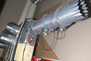
In our first iteration of the project we mapped TJ's motor and sensor connections and removed his main circuit board. It was replaced entirely with an Adafruit DC motor controller, MCP23017 GPIO Expander, and an MCP2221A to link them over USB to our computer using I2C. Power was supplied by an external DC power supply.
We did this because TJ's CPU lives under a black blob on the PCB. We had little hope of interacting with it or using it in any way, so we elected to remove the whole board to better explore its workings and connections to TJ's motors and positional sensors.
Our new system is much simpler. While the CPU may remain useless to us, the original circuit board also carries useful stuff like motor controllers, power supplies, push buttons, a power switch and more. We thought, why not use the stuff we already have? It just requires a bit of hot-wiring.
In our second iteration of the project, we are leaving the external motor controllers and I2C stuff behind. We have another TJ, and this time we're leaving his circuit board intact. We'll be bypassing his original CPU to connect directly to the existing onboard motor controllers, thereby saving greatly on both cost and complexity.
In this simplified arrangement, we have spliced his existing motor controllers into GPIO pins on his new replacement CPU, a Raspberry Pi 4. We are using TJ's existing D battery bank as the power supply for his existing motors and controllers and the pi. A python script running locally on the Pi controls its GPIO. We've chosen a Pi 4 because we'll be doing speech recognition, but for simple motor control any MCU will do!
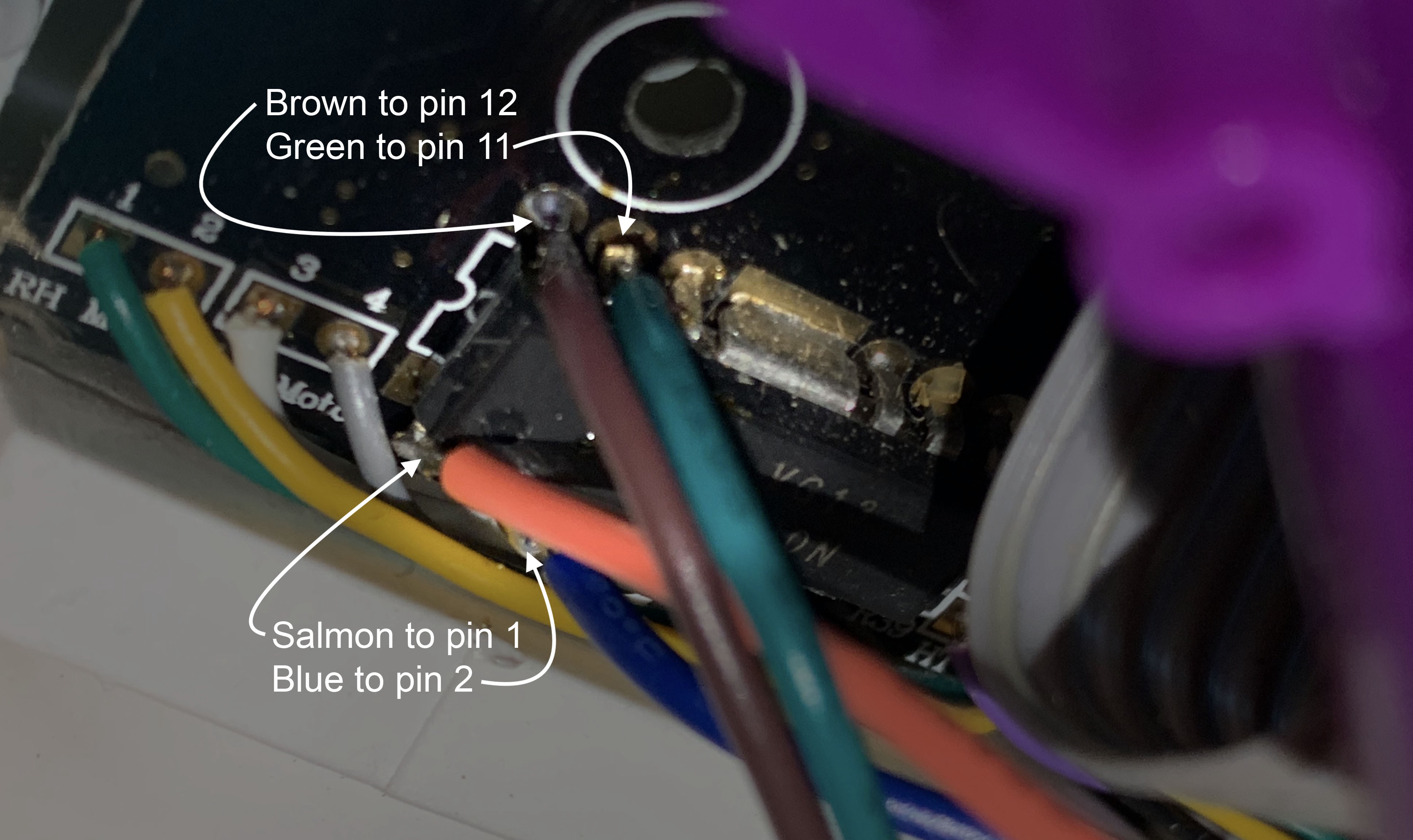
Having learned as much as we have about TJs board, we now know that he has a FAN8100N motor driver. Using 3.3 volts of power, obtained from the board, we are able to run each of TJs motors independently. In this video example TJ is on using battery power, but sleeping, and we use a jumper cable to connect to 3.3v power and each of his pins to run the motors.
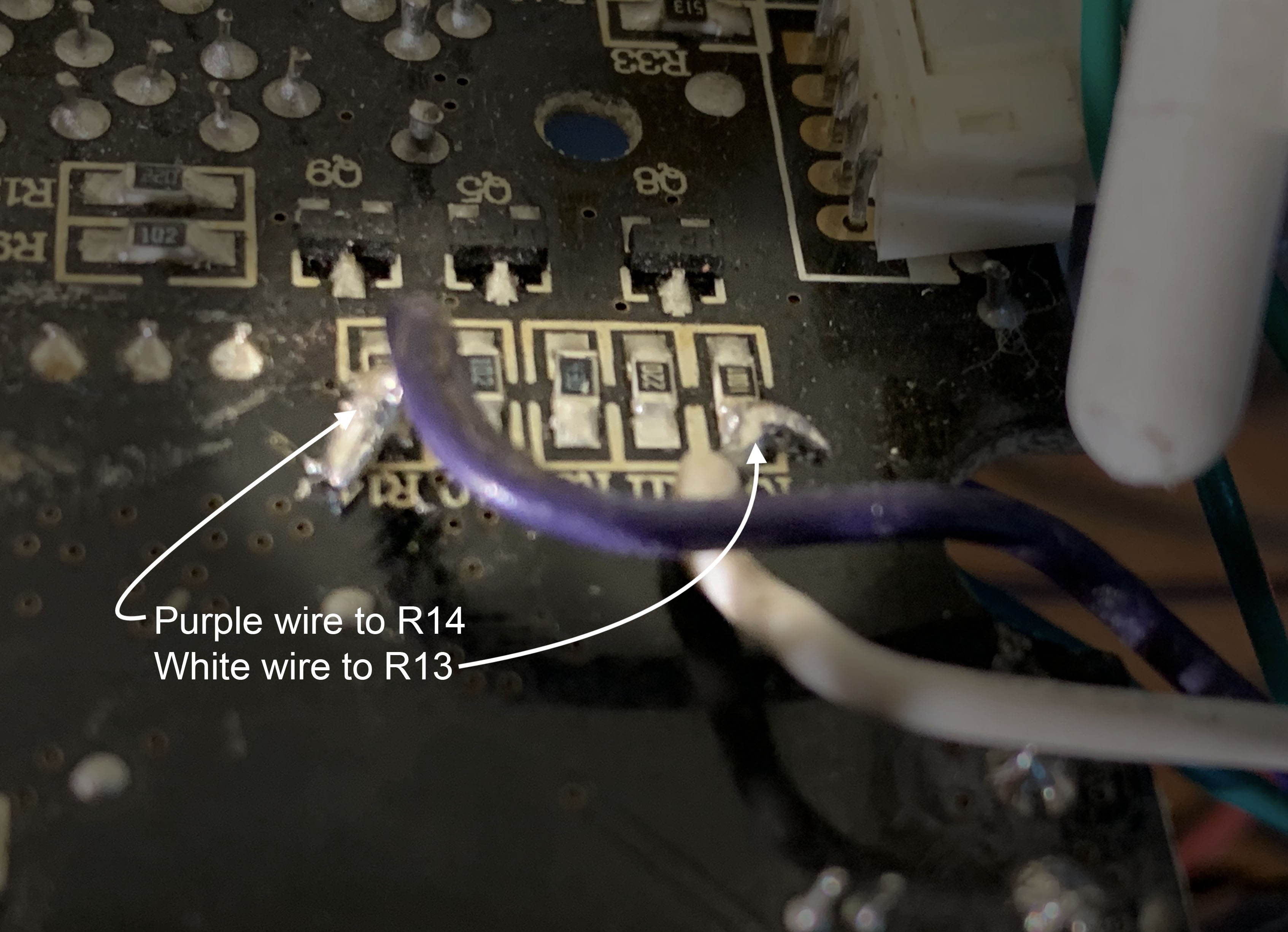
From the data sheet we have the pinout for the chip, which shows pins 12 and 11 are ReverseA and ForwardA. Pins 1 and 2 are ReverseB and ForwardB. These are the pins we will provide 3.3v power to in order to run the motors for the arms and the head. The eyes, ears, and mouth are controlled by an H bridge on the front of the board, and are easily accessed on the back of the board.
TJ knows the position of his gears through the use of five rudimentary rotary encoders. Utilizing a basic form of Gray Code, these encoders report their position as being in one of four possible states using two wires.
Each encoder consists of three metal contacts that rotate over concentric circular tracks on a PCB. The tracks for Contact A and Contact B have metal traces covering only half of their circular path, the other half is bare. You can see the upper and lower half of two encoders in the photos below:
As the encoder rotates, these contacts are connected to ground for half of their rotation, and disconnected from ground during the other half. The innermost track is solid, and connected to ground. As the encoder rotates, the third Contact C stays connected to this ground track at all times.
The outer half circle trace for Contact B is advanced approximately 90 degrees compared to the inner trace for Contact A. This means that Contact A and Contact B will connect and disconnect from ground at differing times throughout one complete rotation. By changing the rotational relationship between the inner and outer trace, it is possible to more precisely identify certain positions within the full rotation, at the expense of resolution in the other positions.
By combining the readings of contact A and contact B, it is possible to know the position of the encoder. The possible states are:
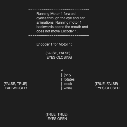
To illustrate a concrete example, let’s look at the single rotary encoder in TJ’s head. We’ll call it Encoder 1. Encoder 1 is attached to the gears that run TJ’s eye blink and ear wiggle loop. It’s buried inside the head gearbox, and since I don’t want to mess up those gears I’ve never opened the head gearbox and thusly I’ve never actually seen Sensor 1, just interacted with its wires. We’ll call those wires A and B. In real life these are the orange and grey wires that come out of TJ’s head and and plug into the side connector of his main board.
We set our GPIO with internal pull-ups and attach wires A and B. When we apply forward power to Motor 1, TJ’s eyes will shut, then open, then his ears will wiggle, and then his eyes will shut again as the loop repeats. At the moment in the loop when TJ’s eyes are fully open, Contact A and Contact B are both disconnected from ground, and both GPIO will read as logical True. Because the half-circle tracks inside the encoder are offset from each other, the state in which both A and B read True exists for only a certain percentage of degrees out of the full rotation of the loop. You can see this rotational loop represented in our comments to ourself in our code.
Encoders 2 and 3 track TJ’s left arm position and head nod position, as controlled by Motor 2. Encoders 4 and 5 track TJ’s right arm position and head turn position, as controlled by Motor 3. All four of them are wired and read in the same fashion as Encoder 1 in the head. Notably, TJ’s mouth has no positional encoding, and its operation depends entirely on timing.
So, as you can see, helping TJ move to any new position is as easy as spinning the correct motor in the proper direction and waiting until the associated encoder reads the correct value, at which point you stop the motor. Our code below shows an example...
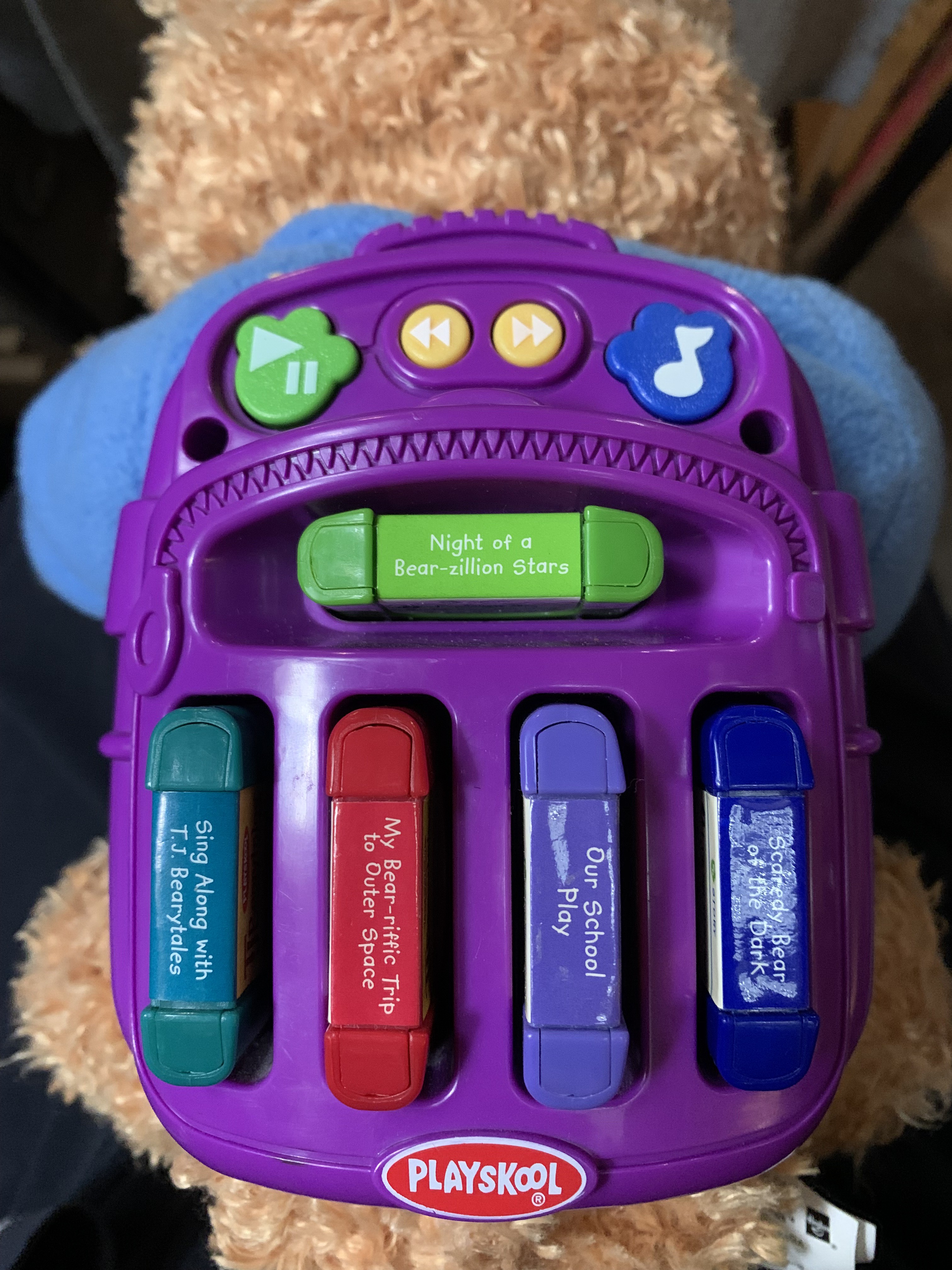
Read more »When we got TJ he was able to play his cartridges and move according to his original programming. But we wanted to help him move on his own. Normally we'd title this section "Controlling TJ," but interestingly that language doesn't seem appropriate for such a friendly bear. Empathy for the machine is much easier to achieve when the machine is fuzzy. Here's a full list of what TJ can do. He can execute seven independent types of movement. Those are:
Incredibly, TJ accomplishes all this using just three small DC motors.
The ears, eyes and mouth are all controlled by a single DC motor located in the gearbox that occupies most of TJ's head. We'll call this Motor 1. His other two motors are located in his body, and control his neck and arm movement. When Motor 1 is run in the forward direction, TJ cycles through ear wiggles and eye blinks. When the motor is run backwards, TJ opens his mouth. Turning the motor forward again will first close the mouth, then resume the ear wiggle and eye blink cycle.
As a result, TJ can only do one of his facial animations at a time. If he is talking, he cannot also blink or ear wiggle at the same time. Additionally, since the eye blink and ear wiggle cycles are linked and only move in one direction, TJ must wiggle his ears once between every eye blink.
The head motor can change directions at any time, which means that TJ can open and close his mouth at any point in the eye/ear cycle, just not simultaneously. For example, to have TJ talk while his eyes are closed, the operator can run the head motor forward though the ear and eye mechanics until the eyes are closed, then cycle the motor backwards and forward briefly to open and shut the mouth. The eyes will stay closed. Once the motor is run forward enough to completely close the mouth, the eye/ear cycle will continue, and the eyes will open again.
The rest of TJ’s motion is accomplished by the two motors in his body. As with the head, the motors are geared to perform one action when running forwards and a different action when running backwards. Motor 2 is responsible for raising and lowering TJ’s left arm when running in the forward direction, and also nodding his head up and down when running in the backwards direction. Similarly, motor 3 is responsible for the movement of the right arm and also the head turning right and left.
Like the eyes and ears mechanism, the head and arm movements are also cyclical and unidirectional. This means that TJ can, for example, lift his arm and stop in an arbitrary position, but he cannot put his arm back down again until it has first been raised all the way to the top, at which point it will continue its cycle down again. The same is true for head turning and nodding.
We took off TJ's plastic backpack to get at the board. The backpack is secured with four size 2.3 triangle security screws. Once the backpack lifts off, the board is exposed.
 |  |
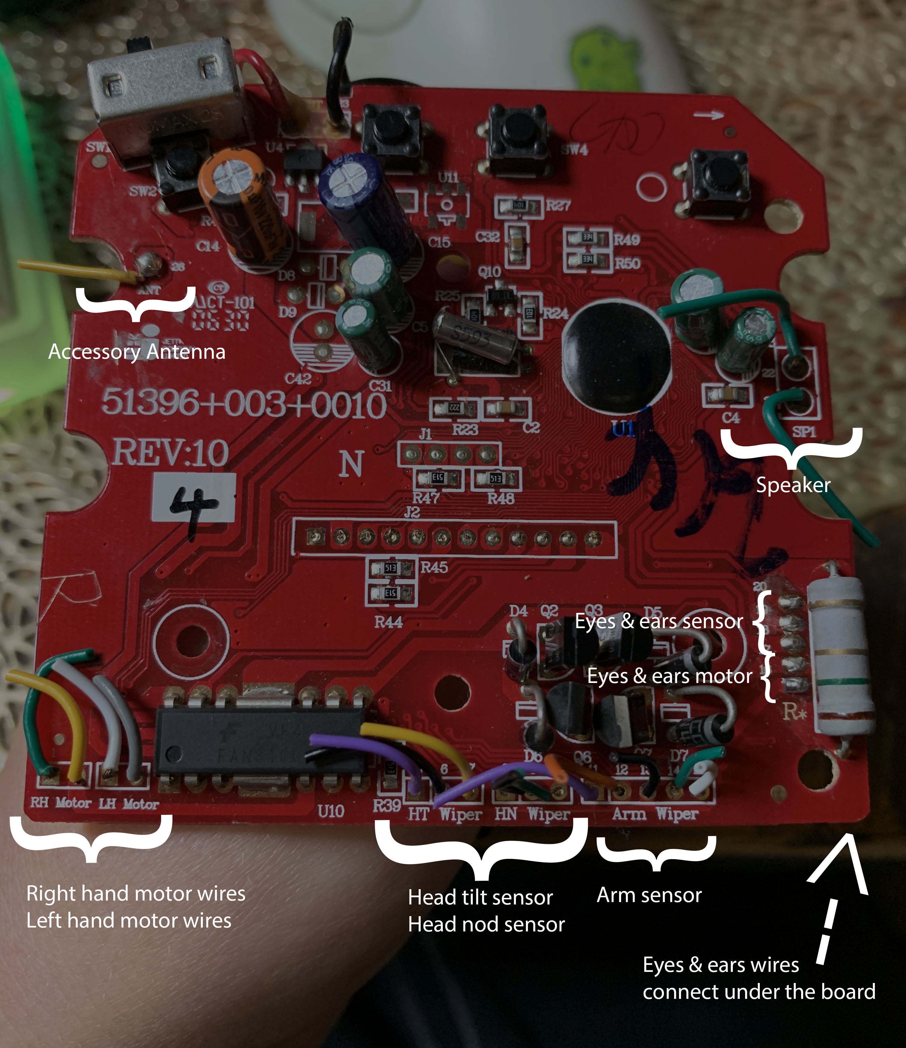
The board is screwed in with two Philips head screws and tips out along the bottom edge. We disconnected and cut the wires leading to TJ's various parts. Below is a photo of the board with its original wires, most of which are clearly labeled.
The wires are listed by pin number in the table below.
| Pins | Use | Color |
|---|---|---|
| 1 | Right Hand Motor A | Green |
| 2 | Right Hand Motor B | Yellow |
| 3 | Left Hand Motor A | White |
| 4 | Left Hand Motor B | Gray |
| 5 | Head Turn Sensor A | Purple |
| 6 | Ground | Black |
| 7 | Head Turn Sensor B | Yellow |
| 8 | Head Nod Sensor A | Red |
| 9 | Ground | Black |
| 10 | Head Nod Sensor B | Green |
| 11 | Left Arm Sensor A | Purple |
| 12 | Left Arm Sensor B | Orange |
| 13 | Ground | Black |
| 14 | Right Arm Sensor A | Green |
| 15 | Right Arm Sensor B | White |
| 16 | Eyes & Ears Motor A | Purple |
| 17 | Eyes & Ears Motor B | Blue |
| 18 | Eyes & Ears Sensor A | Orange |
| 19 | Ground | Black |
| 20 | Eyes & Ears Sensor B | Gray |
| 21 | Speaker A | Green |
| 22 | Speaker B | Green |
| 26 | Accessory Antenna | Yellow |
TJ is using the Coqui TTS English ljspeech VITS model as of last night, and we are running the server locally to increase response time. Now we can have a chat and learn new things about our robot friend, like whether or not he dreams.
TJ is listening to us using Coqui STT, thinking using OpenAI, and speaking using Coqui TTS. As of tonight we can have a real time voice conversation.
We've gotten all of TJ's motors working, and can address each of them. We have positional control over them all, so we can lift and lower his arms, and turn his head side to side and up and down as we please. We're talking to him through a dedicated Discord channel, and his reply gets said aloud as well as written back to the channel. Hi, TJ!


 Here on the board you can see the location of the motor driver.
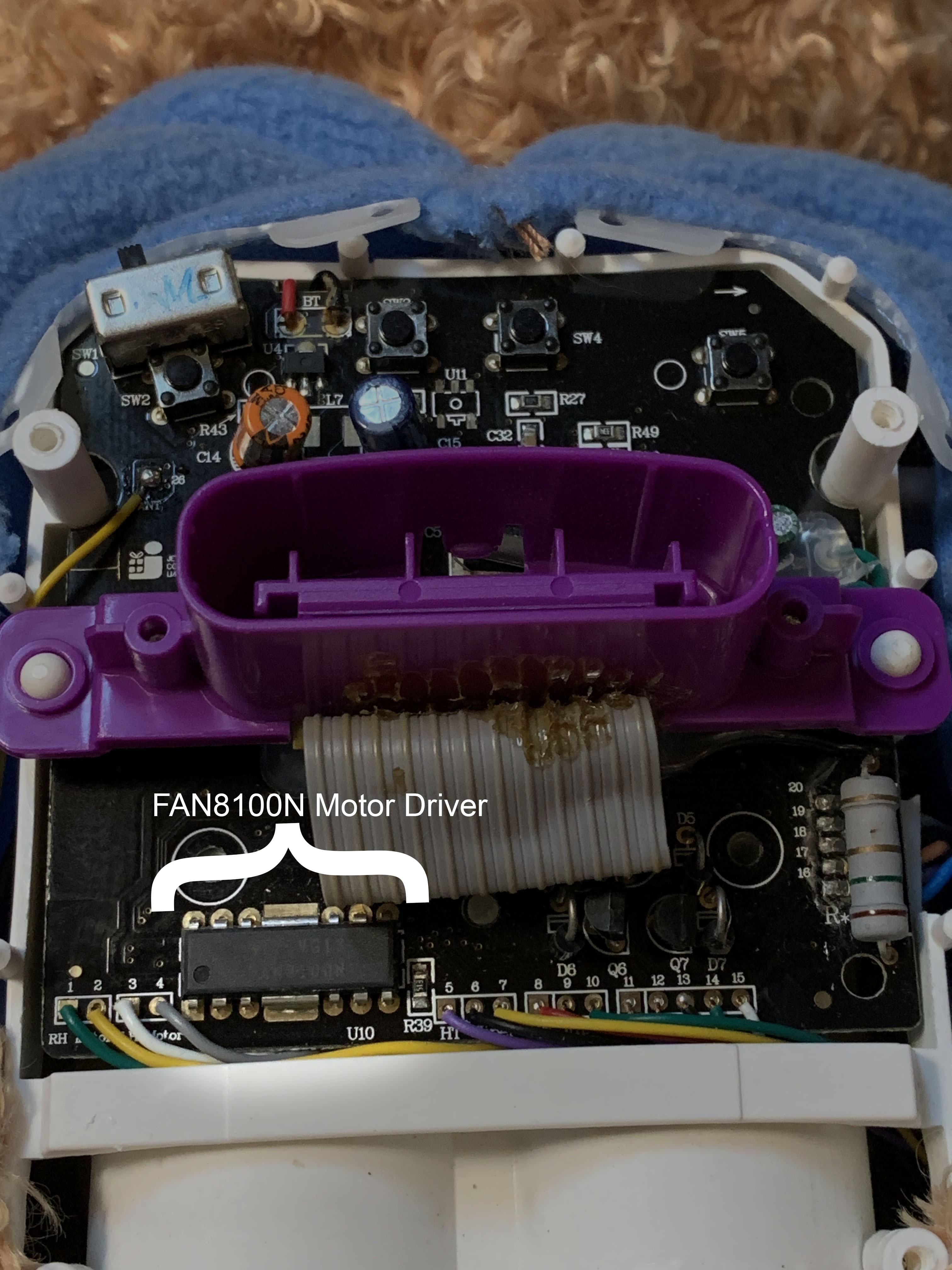 And in this image you can see the location of the H bridge resistors on the opposite side of the board, and the back of TJs buttons, where you can get 3.3v power.
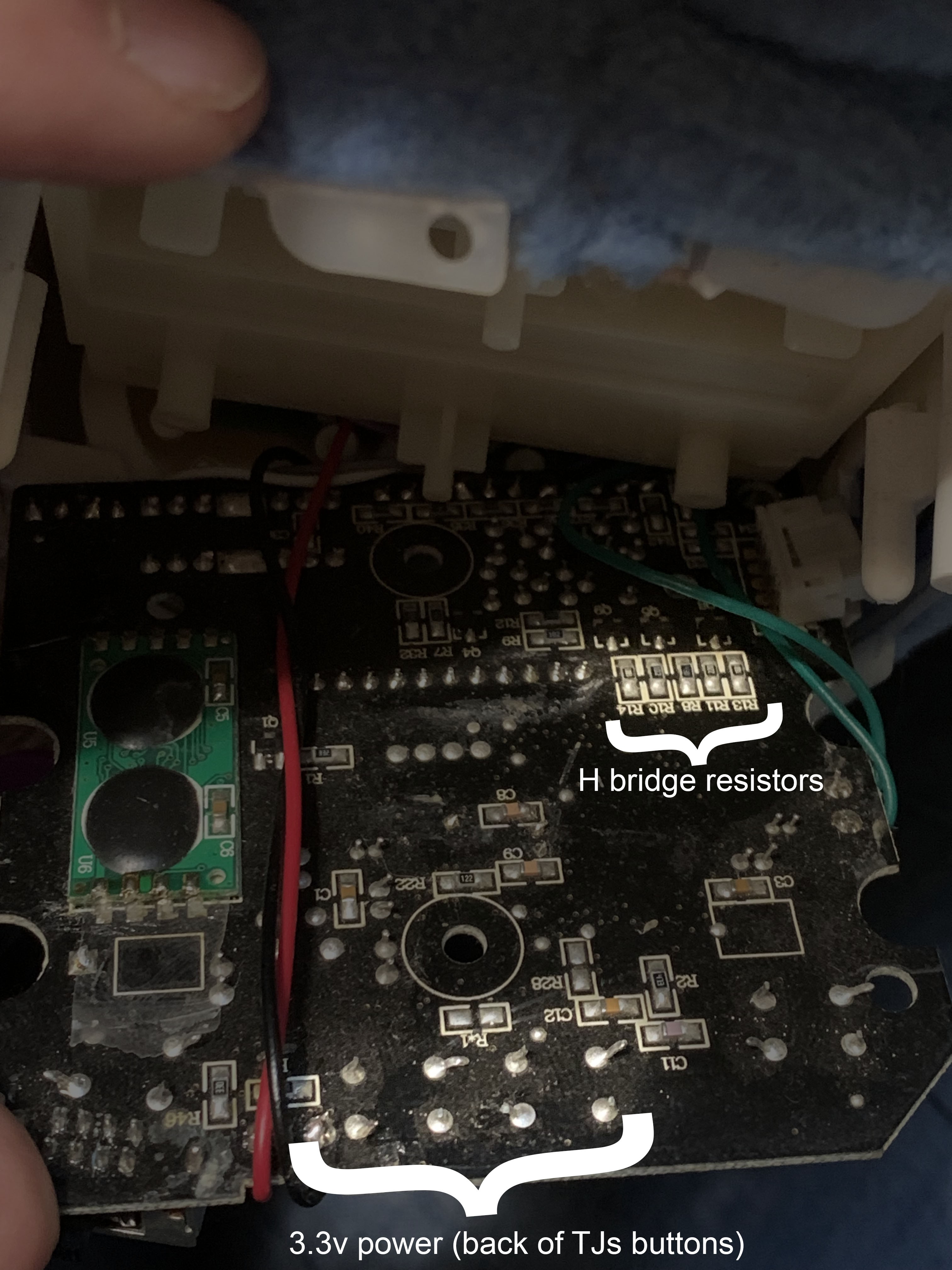

 lion mclionhead
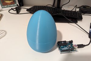
 Krockwell
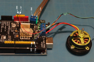
 Kevin LO
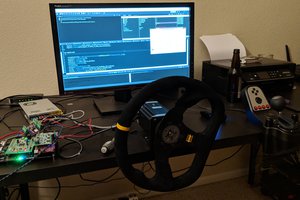
 John Taylor