doctek
Ordering from the usual suppliers, I got VID2905 motors and X27168 motors. For the controllers, I ordered STI6606z and AX120 chips. These items were ordered from different suppliers. Since they are all very cheap and their performance may not be consistent, this strategy of ordering redundantly from various suppliers is one I recommend.
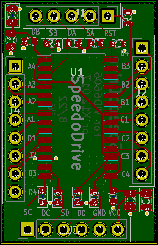
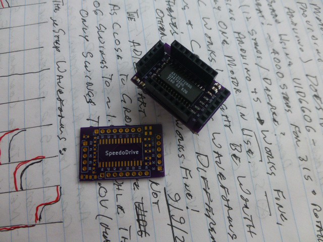
With parts in hand, I studied the data sheets to guide my design. Both controller chips (and similar ones like the VID6606) have the same footprint and the data sheets appear nearly identical. So I designed one pcb to carry the controllers. The data sheets are attached in the Files section. KiCad files and pdfs are also there. Both data sheets state the need for resistors to pull unused inputs to a known level. CMOS doesn't like to have floating inputs! I used 10K pull-down resistors. What this means is that any unused inputs can be safely ignored. The data sheets also state requirements for bulk capacitance. I designed in such capacitance. No further capacitors are needed. By providing these features, my design is fully compliant with data sheet requirements. This is notably superior to simply using a 28 pin SOP generic breakout board. My board may be ordered from OSHPark as SpeedoDrive. The parts placement diagram and paste layer for a stencil are included in the Files. The parts are listed in the Components section.
How to hook up a motor
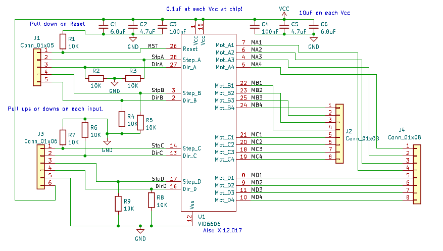
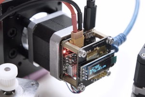
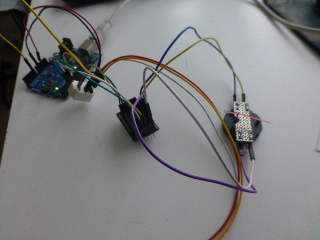
The controller schematic and PCB are shown above. To connect a motor to channel A, hook one coil of the motor to A1 (MA1 on the schematic) and A2 (M2); connect the other coil to A3 (MA3) and A4 (MA4). If you wish to reverse the direction of rotation, switch either pair of wires. That is, move the wire from A3 to A4 and the wire on A4 to A3. Pin SA (StpA on the schematic) is the step input for motor A while DA (DirA) is the direction input. Connect these to digital output pins on the Arduino. The RST pin should go to an Arduino output also. It must be high to enable the controller. Finally, connect GND to ground of the Arduino and VCC to 5 volts. The 5 Volt supply may be from the Arduino if only one channel is to be used. If multiple motors are to be driven, an external 5 Volt supply may be needed. The results look like the picture below.
The Arduino program is ???.ino in the Files section The video shows the STI6606z controller in action in the first sequence. The smooth action is clearly seen. But there is more to the story!
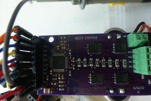
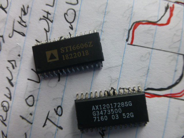
I built two versions of the board: one using the part marked AX1201728SG and one using the part marked STI6606z. I tried both versions with an X27.168 motor and a VID29-05 motor. The parts are shown in the next two pictures. The same Arduino program and hardware hookup was used for all testing.
The rest of the story:
- Using the controller chip marked AX1201728SG, I found that neither of the motors worked reliably. Sometimes, I could get some movement in one direction, but the motor would not reverse. I tried many experiments, including a separate 5V supply and different channels, but nothing helped. I was almost ready to decide the parts did not work reliably! But I kept experimenting.
- Using the controller marked STI6606z, both motors worked perfectly (see video)! So now I believed that both reports of performance were correct: some worked, some didn't. But why? Could I find a smoking gun?
- The two chips were tested using the oscilloscope. I hooked one channel from A3 to ground, one from A4 to ground, and one from SA to ground. At first glance, the drive waveforms look the same.
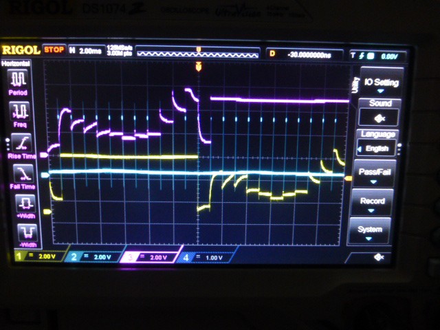
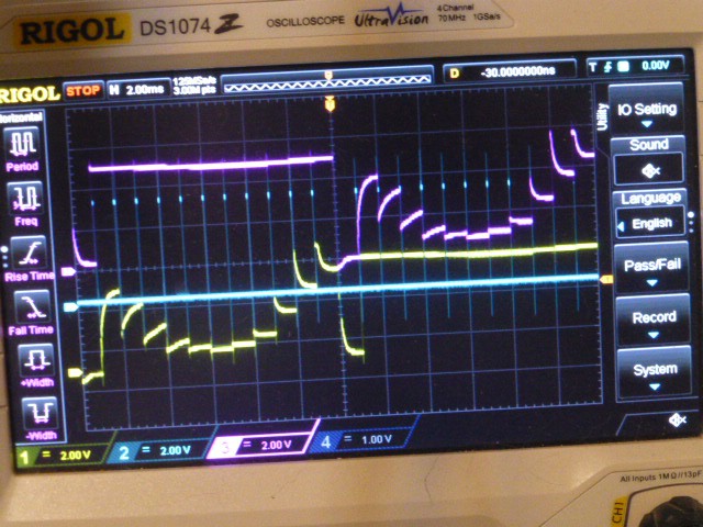
But on closer inspection a clear difference is seen. The low steps from the STI6606 are nearly a volt closer to ground than those of the AX12017! (Ground is indicated by the top arrowhead on the left side of the screen.)
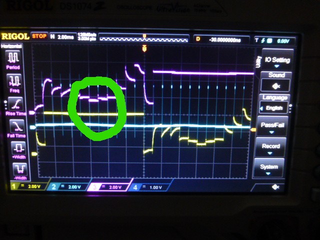
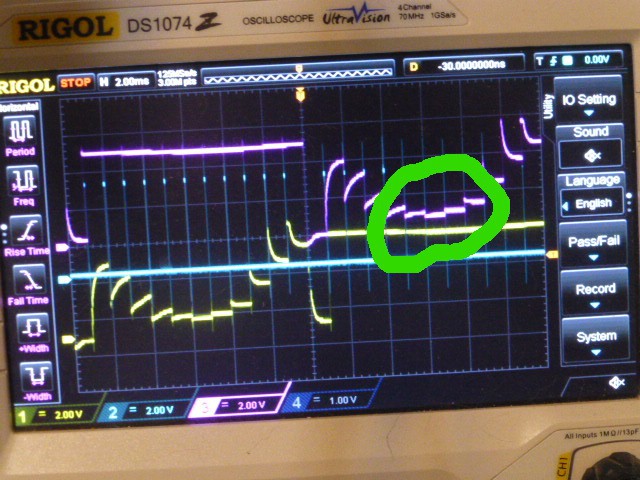
That seems to be the difference between working and not working. Smoking gun indeed! Now the reason why some controller chips work and...
Read more »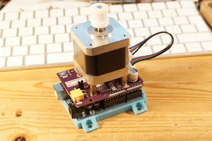
 Jan Neumann