 iHally
Cyberdeck designed around a sick68 keyboard.
- Pi4
- 1920x480 8.8" screen
- 1920x1080 11.6" screen
- 18650 Batteries
- 3s charger
- Water cooling (for no good reason)
- RTL2832U
Unfinished sick68 keyboard feature creeps into designing and ordering parts for a cyberdeck build.
Already have an account? Log in.
To make the experience fit your profile, pick a username and tell us what interests you.
Cyberdeck designed around a sick68 keyboard.
- Pi4
- 1920x480 8.8" screen
- 1920x1080 11.6" screen
- 18650 Batteries
- 3s charger
- Water cooling (for no good reason)
- RTL2832U
water cooler mount v1.3.1.stlwater cooler mount for https://www.aliexpress.com/item/32810596518.html on the rpi4bStandard Tesselated Geometry - 323.23 kB - 10/28/2022 at 11:39 |
|
|
layout 4.0 v2.stlpi mount and keeb layout. two extra keyboard columns. Body is 20mm higher at back and 10mm at the front. Not suitable to printStandard Tesselated Geometry - 260.82 kB - 10/18/2022 at 11:30 |
|
|
layout v3.3.stlpi mount and keeb layout. not suitible to printStandard Tesselated Geometry - 234.46 kB - 10/15/2022 at 00:38 |
|
|
layout v2.8.stlpi mount and keeb layout. not suitible to print or useStandard Tesselated Geometry - 233.48 kB - 10/09/2022 at 14:16 |
|
The weather has lately been swinging in between unrelenting rain and insane heat, completely destroying my schedule and throwing a wrench in my progress.
Also likely to destroy all the components in the project, I've begun integrating watercooling into the deck. The components were purchased 5 years ago with the aim to push the limits of a variable power supply DSP5020. Hoping to use it to charge an unfinished electric skateboard project.
Most definitely completely unnecessary but its going in regardless! I imagine the pump will only have to run sporadically as the water has a high specific heat. Hopefully this should cut down on power usage while still keeping the processor below, 80 deg, its throttle temp.
I was quite surprised how hot the pi got during boot and software updates. I'll be glad for some low noise cooling.
Some haphazard splines later and the mounting points are joined to the copper water cooling block / heat exchanger.
The fit is very snug. The posts for the pi's mounting holes are slightly too short. The hope is that the pressure from the flex of the printed bracket will hold the cooling block firmly against the pi's SoC.
Files for the bracket available on Thingiverse and Thangs.
Next to do is the pump and radiator mounting.
The printed screen rails worked just how they were designed, not sliding at all. There was simply not enough space between moving parts. The second attempt works perfectly sliding in and out and pivoting with little friction and, what appears to be, enough strength. still need a mechanism to hold the screen in the upright position
There is still much to design including the rail on top of the screen and how it fits inside the deck. The height of the deck has been increased, twice now, to accommodate the screen slider under where the pi is mounted. The slider has yet to be integrated into the design of the deck body.
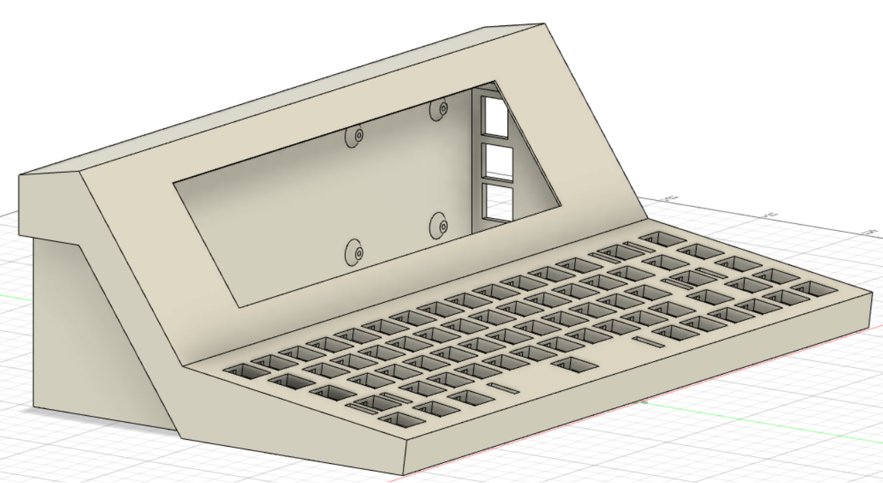
Pi output holes needed a slight adjustment and more tolerance space. 0.2mm clearance was a bit ambitious with the rough print settings I chose to get this large section printed quickly.
The width also had to be increased, which allows space for two extra columns of keys and extra screens or dials next to the main display. Definitely not sad about having more internal space, but I hope it doesnt change the feel/look of the deck too much. There is the possibility of reducing the size of the rails but It would be nice to focus on other parts and revisit this later.
Once everything is fit inside then the design can be broken down into smaller parts to improve printability.
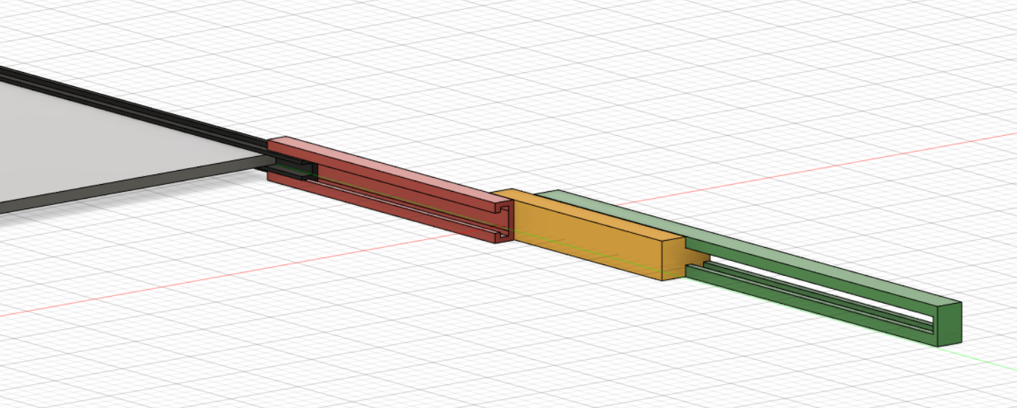
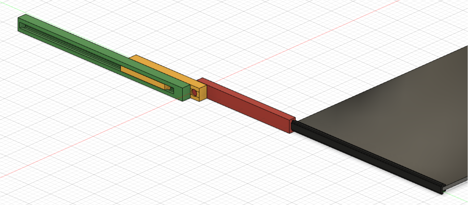
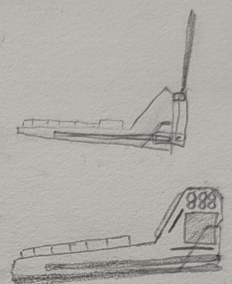
This screen slide idea is finally out of my head and into cad. Completely unproven for functionality or printability but ‘designed’ none the less.
Firstly the screen will be fixed into a rail in black, this can slide thought the screen rail slide in red.
The large green part is the fixed rail that will remain inside the cyberdeck body.
(Realising just now that colour coding would be useful) edit: it is
The main slider in yellow also connects via a hinge to the screen rail slide in red.
Hopefully allowing the screen to slide out of the base of the cyberdeck and then fold 'hinge' upwards to a visible position.
All the lengths need to be checked, I have a growing concern the screen wont reach heigh enough.
Quickly realised, only after thinking about how much vertical space is available for this slider, that the pi is in the way. So glad I didn't invest too much time with the layout of the other internal components.
The side rails of the deck body have been thinned giving more vertical space for the pi's peripheral holes to be mounted higher. Also changed is the side cuttouts, they have been reduced to allow enough space for the screen sliders.
Some input of colour scheme would be very welcome. I'm currently entranced by the idea of creamy white for retro vibes.
Before getting too carried away, I'll start printing off some 50% versions will help validate the current design and see how it looks in real life.
I scrapped, some of the, cobwebs and rust off my fusion 360 skills and got to work.
After more 'learning' that I care to admit, It was good to see the sketches come to life and see how they might feel based on actual dimensions. There is definitely some room for improvement, but the look is close to what I had initially envisioned.
Testing the screen. Don’t let the aliasing mislead you, the resolution on this little 8.8" 1920x480 screen is delightful.
A 'steep learning curve' puts it quite mildly when it comes to the experience of importing stl files and attempting to get a usable sketch out of them. Adding the keyboard layout from the sick68 is beginning to make this project start to feel complete.
Next is working out how to implement a slide out screen into the base and fit the cooling system. Cramming in the batteries and other support boards should be easy and might not require modelling.
But figuring out how to make this 3d printable will definitely melt my noodle
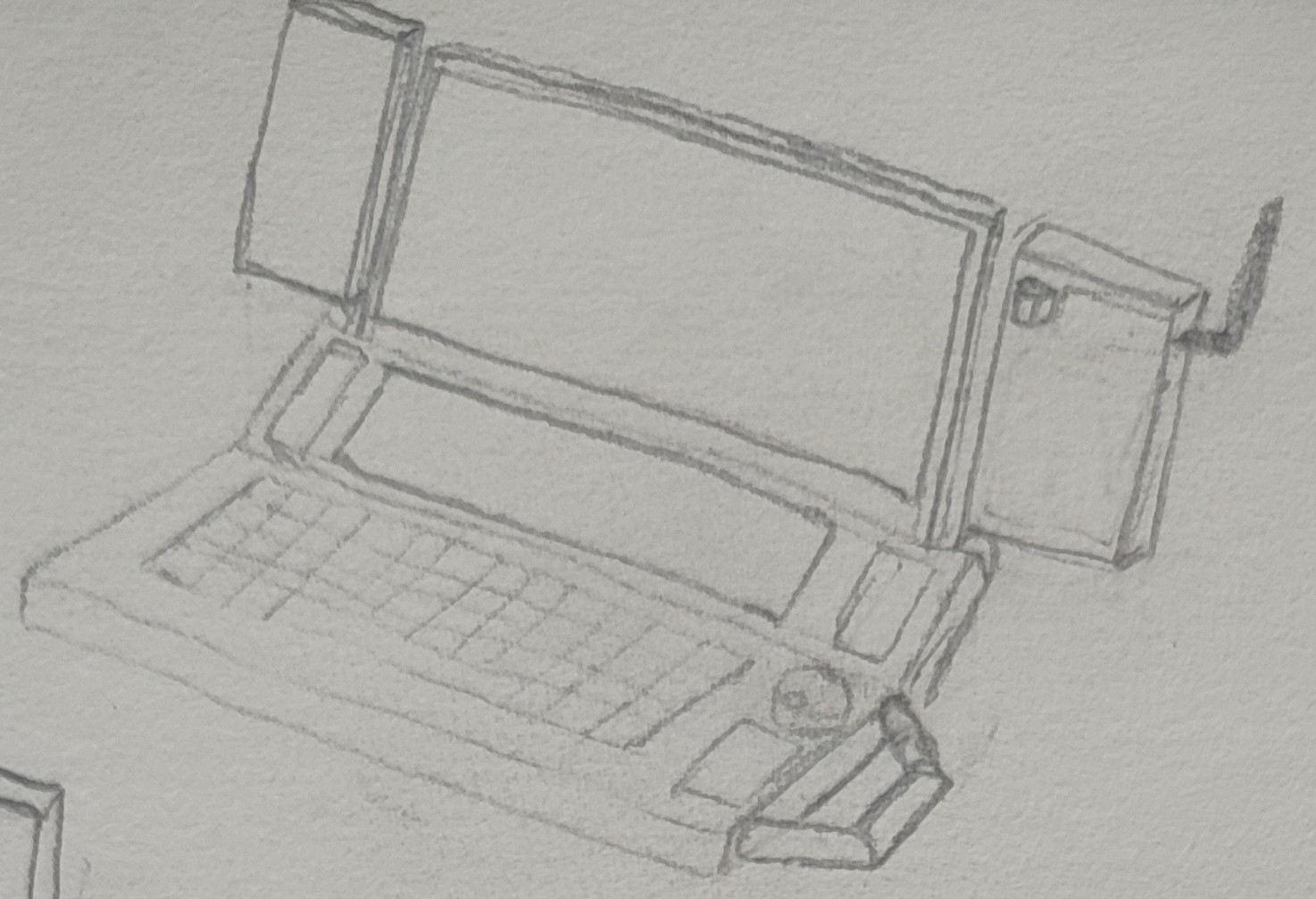
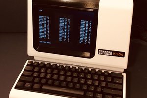
There is a certain aesthetic that is very appealing about the classic Neuromancer cyberdecks. I would like to try and stay true to this while also maintaining some functionality for daily driving.
The main body of the deck will have the 60% keyboard and the wide 8.8” display on a 60deg angle. This should provide a retro feel.
Two fold out modules house the USB hub, low res system information displays, and other HID (dial, slider)
The 11.6” screen can be slid out and hinged up being held magnetically buy adjustable catches to provide a range of viewing angles.
Inside the main body will house the rpi4, screen controller boards, batteries, bms, large screen on a slide with hinge, and the cooling system (pump, radiator, waterblock). Not exactly sure how its all going to fit and maintain any kind of slim portable shape.
Another feature of interest is to use the keyboard as a hid for other systems like a main PC. I’m sure this can be achieved using multiple teensy controllers with a selector switch. There is likely a more elegant solution I have yet to discover.
The last thing of importance is to have a selector for having a HDMI out port. Using a switch to enable the output between the large display and the HDMI out. There are HDMI switch products available however with a quick google I’m sure I can ruin a HDMI cable and create some janky hack.
Next step is to 3D model the parts and try to fit them together


 Michael Gardi
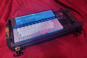
 Garra
Garra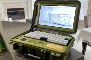
 Kaushlesh C. ( KD9VFU )
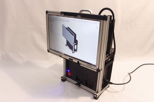
 Roger
Roger