 Real Solar Cars
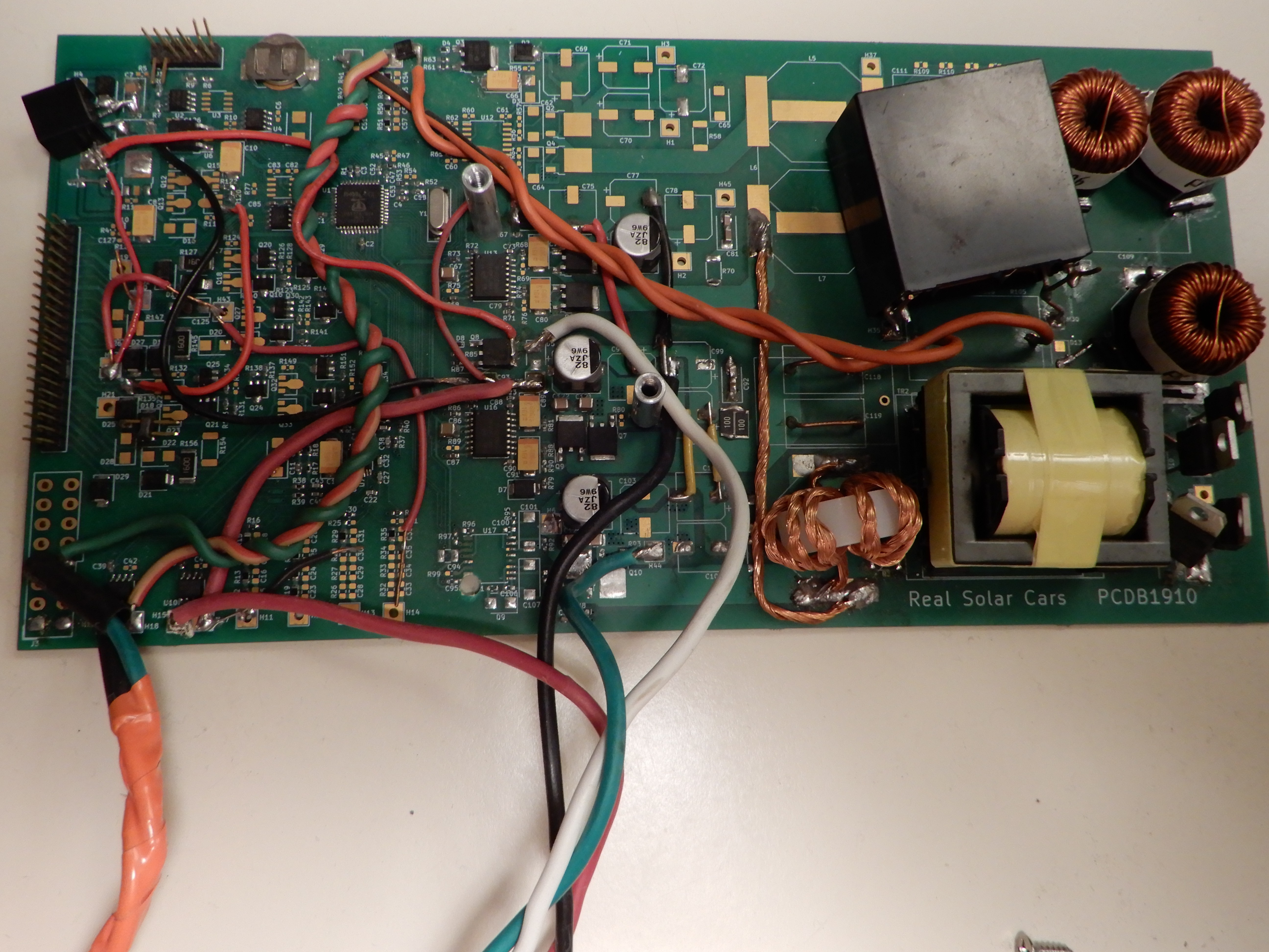
The PCDB1910 met most of the minimum requirements with copious jumper wires installed. Most importantly, it proved that it was possible to DC charge the vehicle without damage or constantly setting the “check engine” light. My experience with this board led to a list of improvements for the next revision.
- Maximum power point tracking is desirable for all solar electric systems. Well, Electrodacus might disagree. But with a small vehicle mounted solar array, the vehicle will consume all the power it can generate. I eventually added MPPT to the software for the first board revision after running without it for a while. It is particularly frustrating to see reduced charge power at low state of charge.
- 12v auxiliary output. 12v charge controllers are a common off the shelf item. But the marginal cost of adding a 12v output to the main board would surely be less than a separate 12v charger. There is also the issue of running two MPPT controllers off one solar array. They may conflict. Many charge controllers expect the solar negative connection to be floating with respect to the battery negative. I was lucky to find a charge controller that worked in this situation. The first board revision using the Propeller 1 was intended to have this feature but it did not have enough current sensors or processor cores.
- 12v adjustable output. The Chevy Volt operates its factory DC-DC converter (replaces the alternator) at a reduced voltage sometimes to save power. The off-the-shelf charge controller I used with the first board revision output a constant 14.4v due to the load of the contactors and battery management system. Reducing this to 13.8v or below may save some energy.
- Energy logging. It’s important to monitor the amount of energy collected to detect problems This data will also be useful for promoting this unusual solar car system. The first board revision used the battery backed RAM of a DS1307 to maintain a kilowatt-hour count. Now, I use a Raspberry Pi that logs data from the solar charger board as well as the vehicle’s battery management system. It even uploads to the realsolarcars.com website.
- Automatic day/night switching sounds trivial at first. But when it comes to programming the microcontroller, it becomes complicated. Most charge controllers can cycle on and off at dawn without issue. That is a big issue when charging a high voltage drive battery. The high voltage charger should be turned on only when there is enough available power to overcome the overhead of the contactors and battery management system. And the number of on/off cycles should be minimized because that involves closing the contactors and a high voltage precharge.
- Contactor coil economizer. Contactors require a certain amount of voltage to close. But once closed, they will stay closed with much less voltage. If the voltage can be reduced during contactor operation some power can be saved. The Chevy Volt does not economize the contactors. This may be a bad idea while driving; the vibration could cause the contactor to open unexpectedly. And there is not much motivation to economize the contactors when charging from grid power.
- Electromagnetic interference. Since the solar panels are mounted extremely close to the radio antenna, any electromagnetic interference from a solar charger could have a significant impact on radio reception.
- Function as a logic analyzer for development work. The best way to figure out the how to operate the vehicle’s contactors is to put the vehicle in different states and observe what it does.
- Designed for an enclosure. Since dust and moisture is common in the automotive environment an enclosure with an IP68 rating would be ideal. However, the space available in the vehicle is fairly restricted. Also, the board needs to dissipate heat well. So a plastic enclosure would not be as desirable. Most power inverters use an extruded aluminum enclosure for this reason. As a compromise I designed the board to fit into an IP66 rated Bud EXN-23366 enclosure.
Discussions
Become a Hackaday.io Member
Create an account to leave a comment. Already have an account? Log In.