Close
0%
0%

strong servo motor with a wiper motor

Here is how to reuse cheap and strong wiper motors to make an extremely powerful servo motor (linear actuator for exemple)

Similar projects worth following
As you may know if you follow my projects, after a small solar tracker, I have in mind to scale up to a bigger solar panel.
To do so I need stronger linear actuators. Stronger ones can be quite expensive...

So Why not build your own reusing a wiper motor ?

Let's start by a video 

the idea

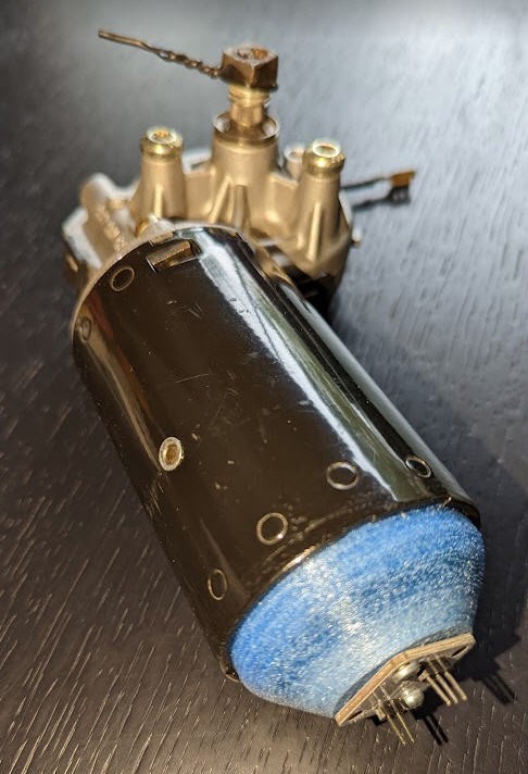
I had an old wiper motor made by Bosch. It's the same type as this one.

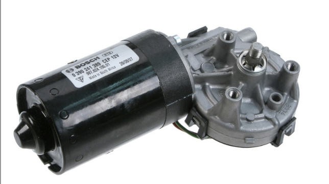
They are very powerful, they draw 2 to 3A, do not run very fast but have really a lot of torque, much more than what I would ever need to rotate a solar tracker (even a big size one !).

However these motors are DC ones without any solution to control their position. 

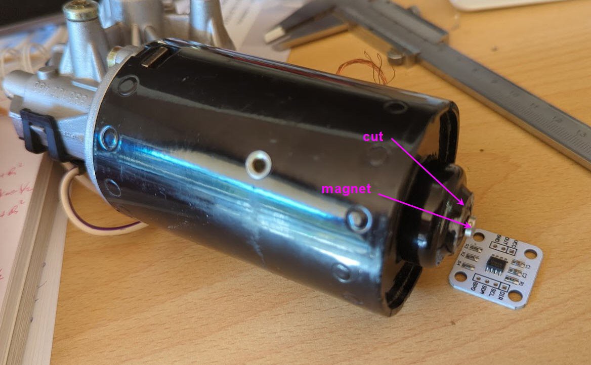
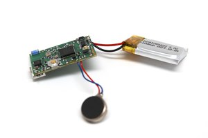
So I decided to add a cheap 12bits magnetic encoder AS5600

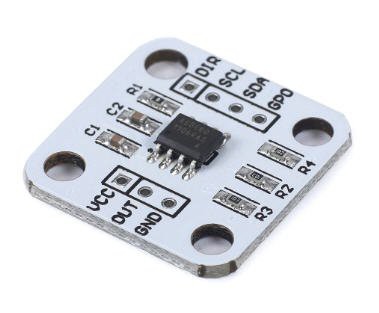
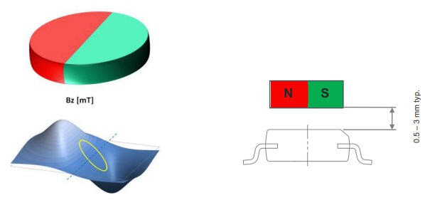
This chip is equiped with a precise hall sensor and allows to detect the angualr position of a diametric magnet "flying" above it (ideally less than 3mm above the chip).

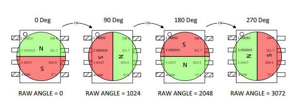
I decided to install the magnet directly on the motor shaft (not the wiper shaft) to get the maximum precision.


mounting the magnet

The first operation was to cut the end cap of the motor to access the motor shaft.

Unmount the motor, remove the cover. Then drill the bottom (not the bearing...) and finish grinding it so that the shaft will be visible.

Now, print the sensor holder and glue it in place. 

Also on thingiverse: https://www.thingiverse.com/thing:5552935

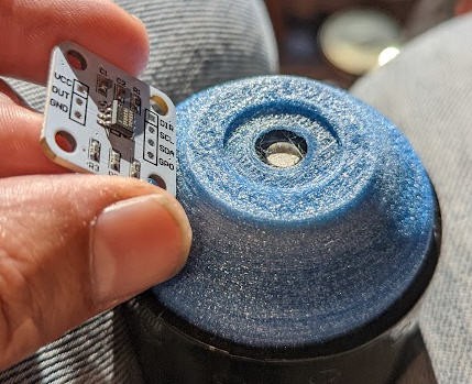
And finally glue the magnet and fix the sensor in place

Your motor is now a servo motor !
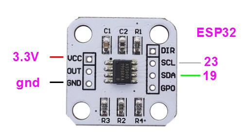
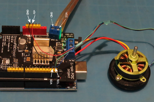
wiring the AS5600

this device is an I2C sensor and needs only 4 pins to interface with ESP32 MCU


Adding a driver board 

To drive this motor you will need a quite powerful H bridge driver. I chose the IBT-2 chineese driver.

It's a very powerful one said to handle 43A.

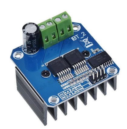
It's composed of two half bridges BTN7970

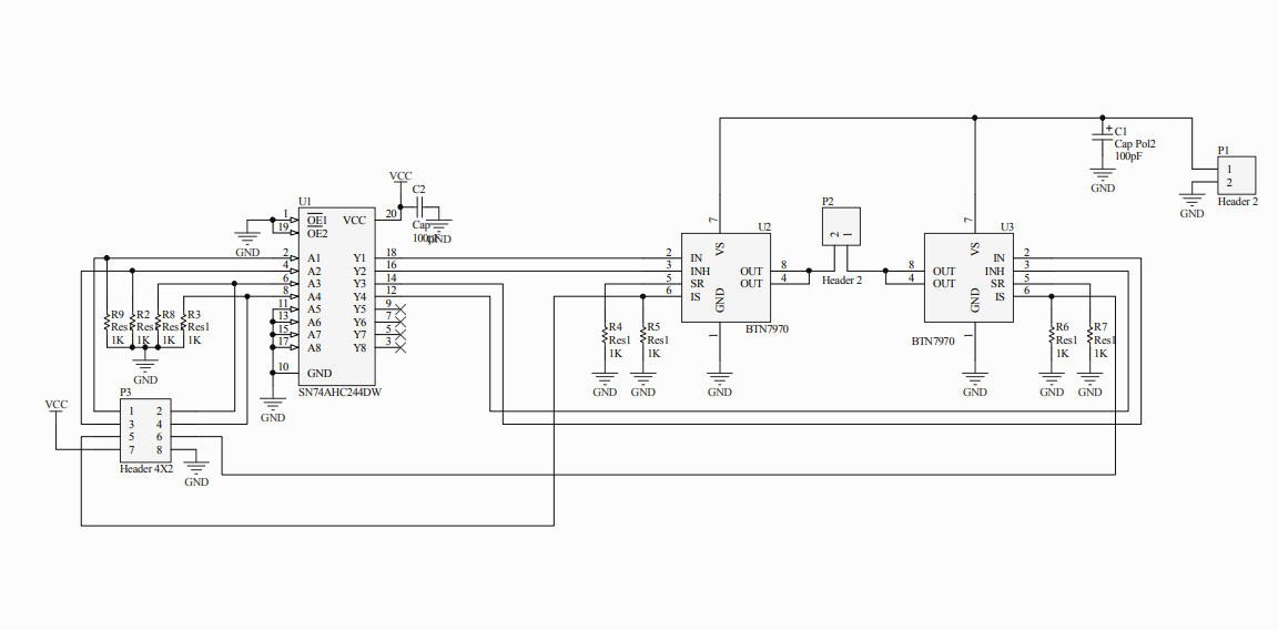
Using this chip is quite easy. I followed this excellent tutorial but replaced the arduino by an ESP32.


Wiring IBT-2 with ESP32

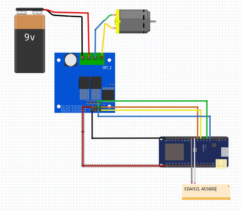
The big terminal blocks are connected to the motor and the DC power (12V in reality !)

The pin headers are connected as on the drawing to the ESP32 pins

  •  IBT-2 pins  7 (VCC) to ESP32 3.3V (yes it works at 3.3V)
  •  IBT-2 pin 8 (GND) to GND (both 12V ground and ESP32 ground)
  •  IBT-2 pins 5 (R_IS) and 6 (L_IS) not connected
  •  IBT-2 pin 1 (RPWM) to ESP32 pin 18  (PWM output pin for Right half bridge)
  •  IBT-2 pin 2 (LPWM) to ESP32 pin 5  (PWM output pin for Right half bridge))
  •  IBT-2 pin 3 (EN_R) to ESP32 pin 17 ( Enable pins R )
  •  IBT-2 pin 4 (EN_L) to ESP32 pin 16 ( Enable pins L )

ESP32 firmware 

Example firmware is available on my Github

The code is extremely simple and only shows how to read the sensor, drive the motor and apply a PID control loop to precisely position the motor at any number of turn you want (integer + fractional turn of the motor shaft).

reading the AS5600

I do use Rob Tillard's AS5600 library. It is really simple and does the job !

A few lines are enough to read the sensor and detect "zero crossing" for full rotations counting:

 //AS5600


  rawValue = as5600.readAngle();
  if (((rawValue - prevRawValue) < -999) && CW) nbRot++ ; //apply hysteresis to detect each full rotation (4095 <--> 0)
  if (((rawValue - prevRawValue) > 999) && !CW) nbRot-- ;


  prevRawValue = rawValue; //save the rawValue for next iteration

driving the motor

no library but simple code as well !

two PWM signals enter Left and Right H bridges.

void runMotor(void)
{
  if (pwmSpeed > 0)
  {
    ledcWrite(0, pwmSpeed);
    ledcWrite(1, 0);
    CW = true;
  }
  else
  {
    ledcWrite(0, 0);
    ledcWrite(1, -pwmSpeed);
    CW = false;
  }
}

the pwmSpeed variable can be positive or negative. Positive is for CW rotation and negative CCW.

each pwm signal has a range 0-2047 on 11 bits and a frequancy of 24kHz

They are "hardware PWM" embeded into the ESP32

  ledcAttachPin(RPWM_PIN, 0); // assign PWM pins to channels
  ledcAttachPin(LPWM_PIN, 1); // assign PWM pins to channels
  // Initialize channels : ledcSetup(uint8_t channel, uint32_t freq, uint8_t resolution_bits);
  ledcSetup(0, 24000, 11); // 24 kHz PWM, 11-bit resolution (range 0-2047)
  ledcSetup(1, 24000, 11);

Now that we can rotate the...

Read more »

PCB_holder_WiperMotor.STL

AS5600 holder for Bosch wiper motor

simplify3d_stl - 521.47 kB - 10/07/2022 at 17:16

Download

  • firmware V2 "strong PID"

    JP Gleyzes10/12/2022 at 07:40 0 comments

    The version2 of the firmware is accessible on my Github

    It's a "strong PID" tuning where the motor reaches its target. in one shot.

    PID coefficients are quite agressive, but overshoot is very limited and motor does not oscillate.

     //PID stuff
      input = getMotorPos();
    
      Kp = 6000;                     // start with an almost fully proportionnal PID
      Ki = 20.;
      Kd = 100. ;
    
      myPID.SetTunings(Kp, Ki, Kd);
      myPID.Compute();

    A compensation factor of the "inertia" of the rotor is introduced (should be tuned if you change motor).

    #define INERTIA  1155./4096. //inertia of motor when stopping (PID over shoot on sensor position)

     This acts as a bias to setpoint value.

     //turn the PID on
      setpoint =  targetRot - INERTIA; //setpoint is this target number corrected of the INERTIA bias
    

    Results are impressively good !

  • firmware V1 (soft PID)

    JP Gleyzes10/12/2022 at 07:35 0 comments

    The first version of the firmware is accessible on my Github

    It's a "soft PID" tuning where the motor reaches progresively its target. 

View all 2 project logs

Enjoy this project?

Share

Discussions

Daniel Simu wrote 01/28/2023 at 12:02 point

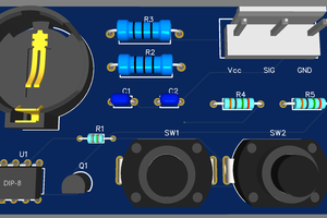
Hey, thanks for the clear tutorial and useful prints! I have made one of these myself, and it mostly works great!


However, I am having one issue. Every now and then (about once every 30 seconds on average) the function as5600.readAngle() gets stuck and takes 1002ms to return. I have this issue both with your example code, as well as with my own implementation. Of course this completely messes up my readings, as in the meanwhile the motor has made multiple revolutions and I've lost track of the position of the output shaft.

Have you had this problem, or might you know what's going on?

I'm running this on an ESP32 btw..


Thanks!

  Are you sure? yes | no

JP Gleyzes wrote 01/28/2023 at 12:29 point

Hi,

No I never got this behavior... I have tested this setup during 20 or 30 minutes without any issue.

Does it occur also on a simple loop limited to only the reading of the sensor ?

Could you try with another AS5600 chip ? 

I don't see any reason for the sensor to get stuck ... may be too long wires for I2C lines ?

  Are you sure? yes | no

Daniel Simu wrote 01/28/2023 at 12:41 point

Thanks for the swift response!

I have not yet tested with a loop limited to only reading the sensor, will check that soon.

I have another AS5600 lying around, so I can give that a try.

Thanks again!

  Are you sure? yes | no

Daniel Simu wrote 02/20/2023 at 15:41 point

It turned out to be an issue with i2c disconnecting because of the motor vibration, see the discussion here:
https://github.com/RobTillaart/AS5600/issues/28#issuecomment-1408127923

  Are you sure? yes | no

reiv91 wrote 12/02/2022 at 18:10 point

Hi, i am very interested in your project, i would like to use this big servo with a radio module because i want to build a radio control to open and close a window so the motor has to stop on two specific positions. do you think it is feasable?

  Are you sure? yes | no

JP Gleyzes wrote 01/28/2023 at 12:30 point

Yes for sure it could be easily feasible.

  Are you sure? yes | no

Bharbour wrote 10/12/2022 at 18:19 point

Your description matches the motors that I am using too. I also have a 1:4 reduction via a toothed belt after that. The motors have been in use for a while and there is a significant inertial load due to the mechanical design. There is definitely backlash in my motors. I am using 4096 count/rev encoders on the shaft between the motors and the belt reduction. Your solar tracker project looks like fun!

  Are you sure? yes | no

JP Gleyzes wrote 10/12/2022 at 19:47 point

Couldn't you calibrate the backlash by software ?

I did calibrate the "inertia" of the rotor and get now quite precise results. I believe that these motors will be perfect for a bigger solar tracker where absolute accuracy is not required.

But for astronomical application (antenna pointing) it"s probably a must...

What was tricky for me is the "deaband" that this motor has when pwm value is too small to rotate the motor and stalls it.

BTW : my setup is currently with a "no load " condition. I will probably enter in difficulties when I will load the shaft... So thank you for your comments... I'll have to take care of backlash as well !

  Are you sure? yes | no

Bharbour wrote 10/12/2022 at 22:25 point

My application can tolerate a few degrees of error, as the antenna beam width is about 20 degrees, so I did not try to cancel the error via software. If it was a telescope, it would be a different story.

Where the gear backlash caused me problems was the way that it interacted with the "deadband" and integrator windup. Small stopping errors cause the integrator to grow to the point that the PWM overcomes the static friction and by the time the backlash has closed enough to move the encoder, stuff is moving fast enough to overshoot. The overshoot corrects itself in the opposite direction, with the same problems. Pretty soon it is oscillating to the point that the motor driver overcurrent shuts the driver down. The driver chips I am using are set to about 8Amps as I remember. Those motors have a fair appetite!

With your setup having the encoder on the motor shaft, the backlash should be less of a problem. The servo may hunt inside the backlash, increasing the average current draw, but it should easier to tune to be slightly overdamped. Integrator windup interacting with the deadband will still be an issue though. Good Luck!

  Are you sure? yes | no

Bharbour wrote 10/12/2022 at 15:21 point

Having the encoder on the motor shaft is important here. I built a satellite antenna rotator using similar motors that has the encoders on the output shafts of the gearboxes, and the gear backlash and the output shaft slop makes it very difficult to tune the PID gains.

  Are you sure? yes | no

JP Gleyzes wrote 10/12/2022 at 15:38 point

On my motor I have pretty much no backlash. It's a single worm gear + one normal gear inside.

But having the encoder on the motor shaft does increase the accuracy as the motor has to mak 52 turns for 1 full rotation of the output shaft.

As I can detect all the 4096 pulses on the motor shaft this gives a theoritical accuracy of 1/(4096 * 52) on the output. (but backlash will still be there... I do believe that you can balance it as we know on which direction is going the shaft. (See my log #2) 

  Are you sure? yes | no

Doug LaRue wrote 11/05/2022 at 19:04 point

On the motors I used there was a screw on the end of the worm gear which let you adjust the worm gear to worm wheel gear. I laser cut some acrylic gears, attached one to the output shaft and the other on a POT and it worked pretty well for remote control steering of a PowerWheel car. But thanks to @JP Gleyzes post I see now I can mount the magnetic encoder to the motor shaft for a much cleaner and more accurate solution. 

  Are you sure? yes | no

Similar Projects

Does this project spark your interest?

Become a member to follow this project and never miss any updates