 ekaggrat singh kalsi
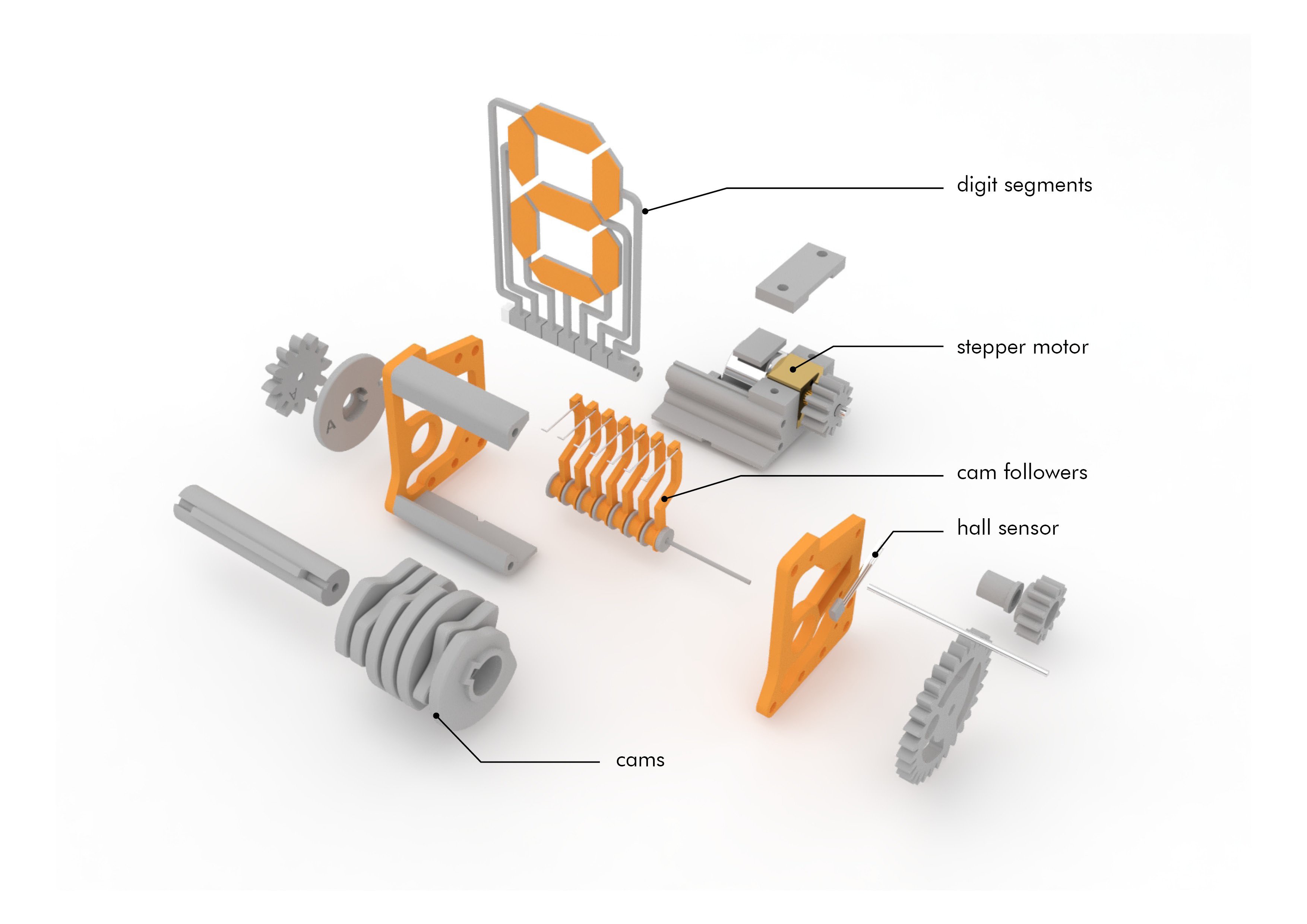
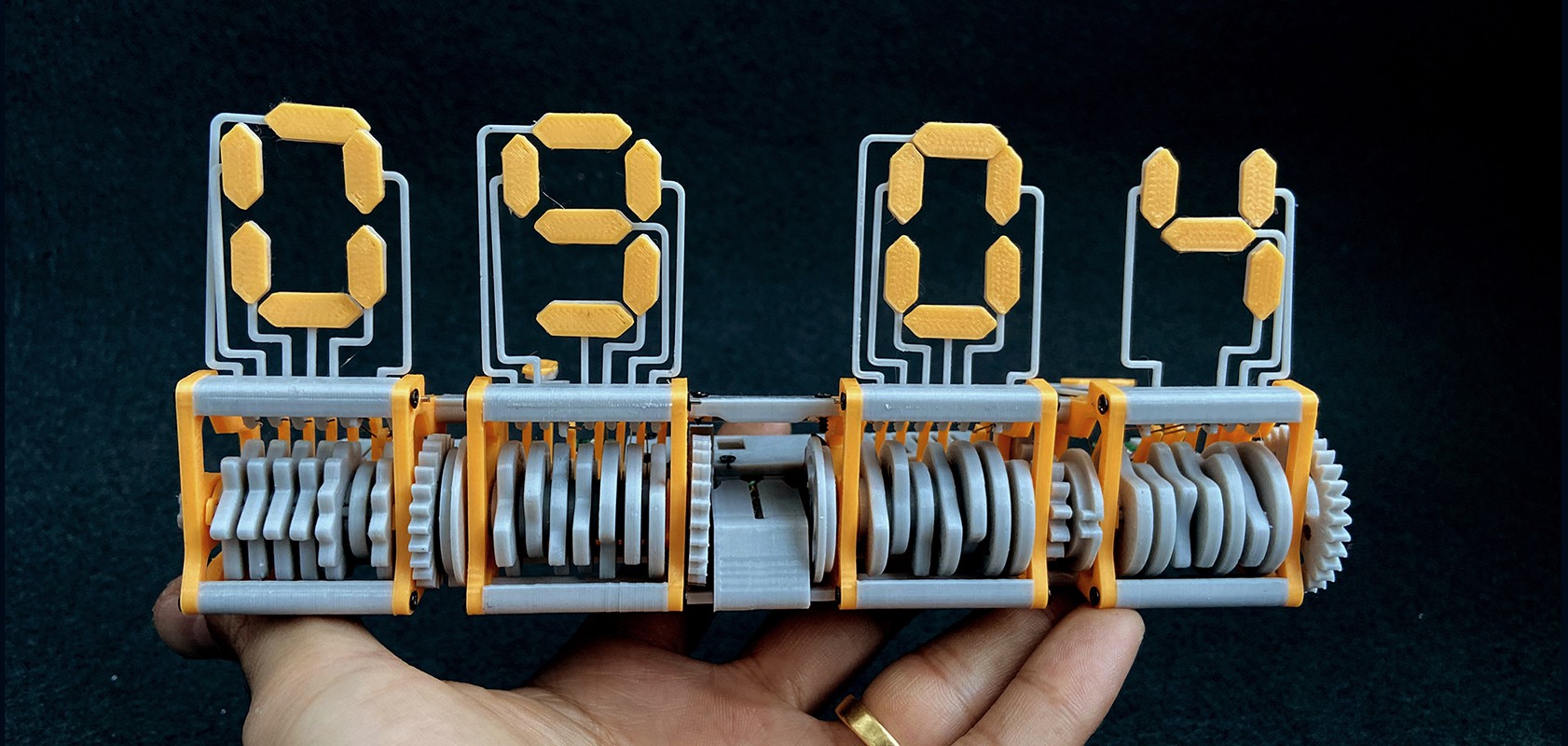
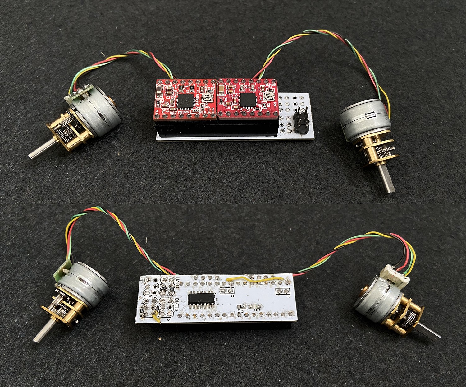
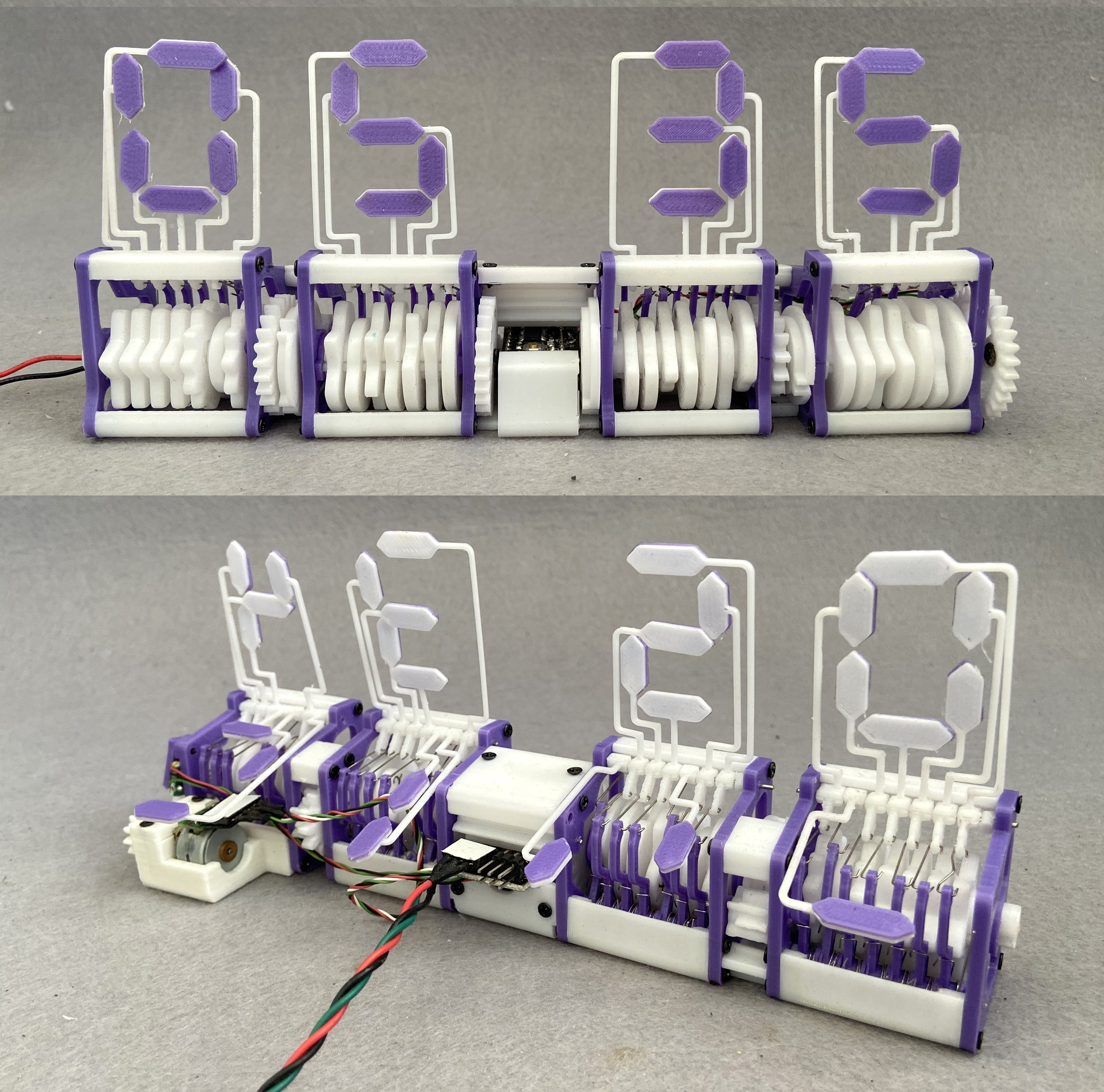
The clock consists of 7 segments which are driven by seven cams. The cam push the followers which in turn lift the segments at the right moment to display the digit needed. The modules work in pairs. The entire clock is driven by a attiny 84 and two a4988 stepper drivers. The first module is driven by a 15mm geared stepper motor which turns it every 1 minute. After a full circle of the module the second module is driven by a carryover gear. The third module is again driven by a stepper motor which turns every one hour and then carry overs to the forth module at 10 and 12 o clock.
The modules run in pairs making it easier to adjust the time. The time is adjusted by two buttons present in the center of the clock. The over all dimensions of the clock are 191 X 52 X 84 mm Or 7.5 x 2 x 3.3 inches
Circuit board:
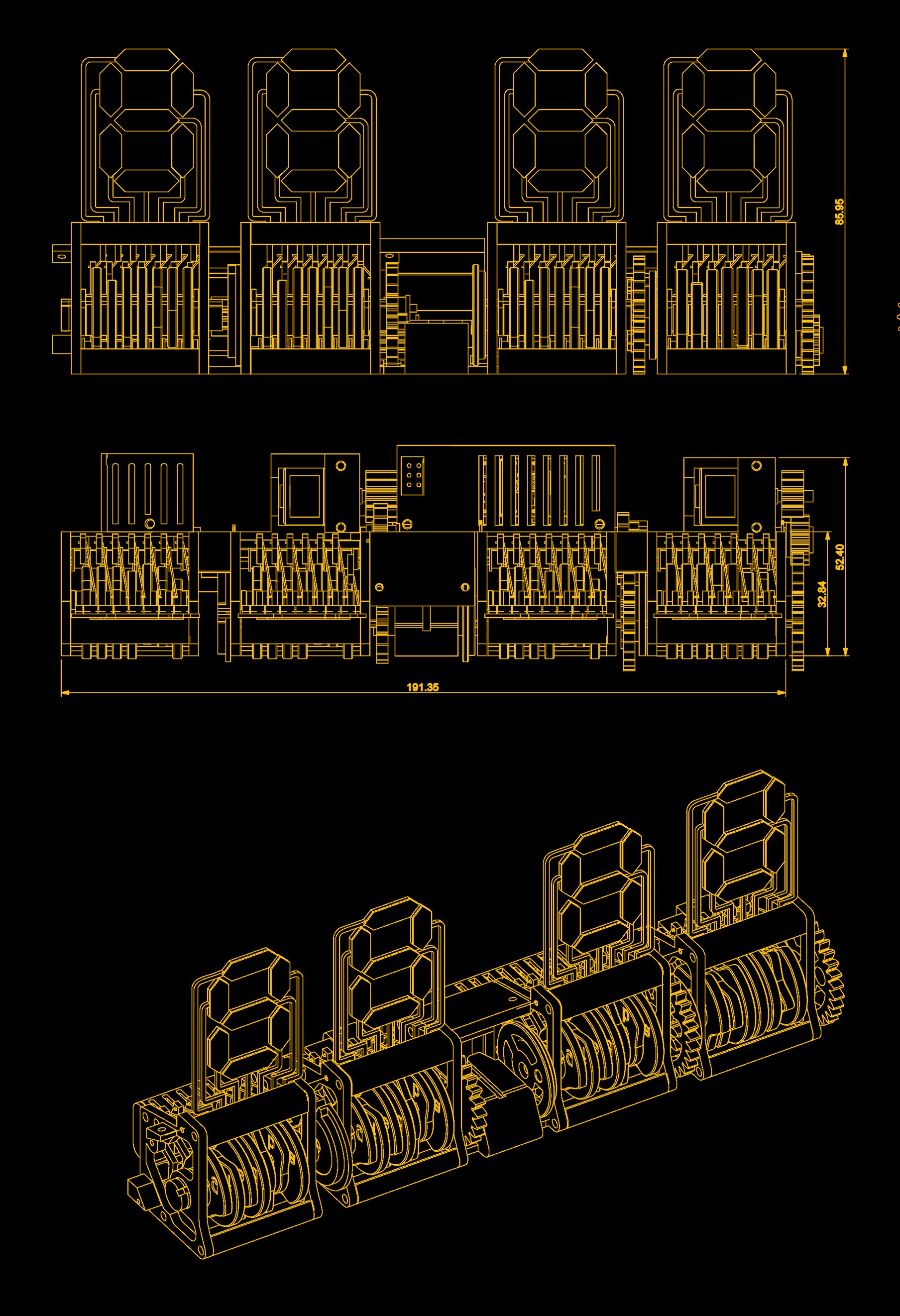
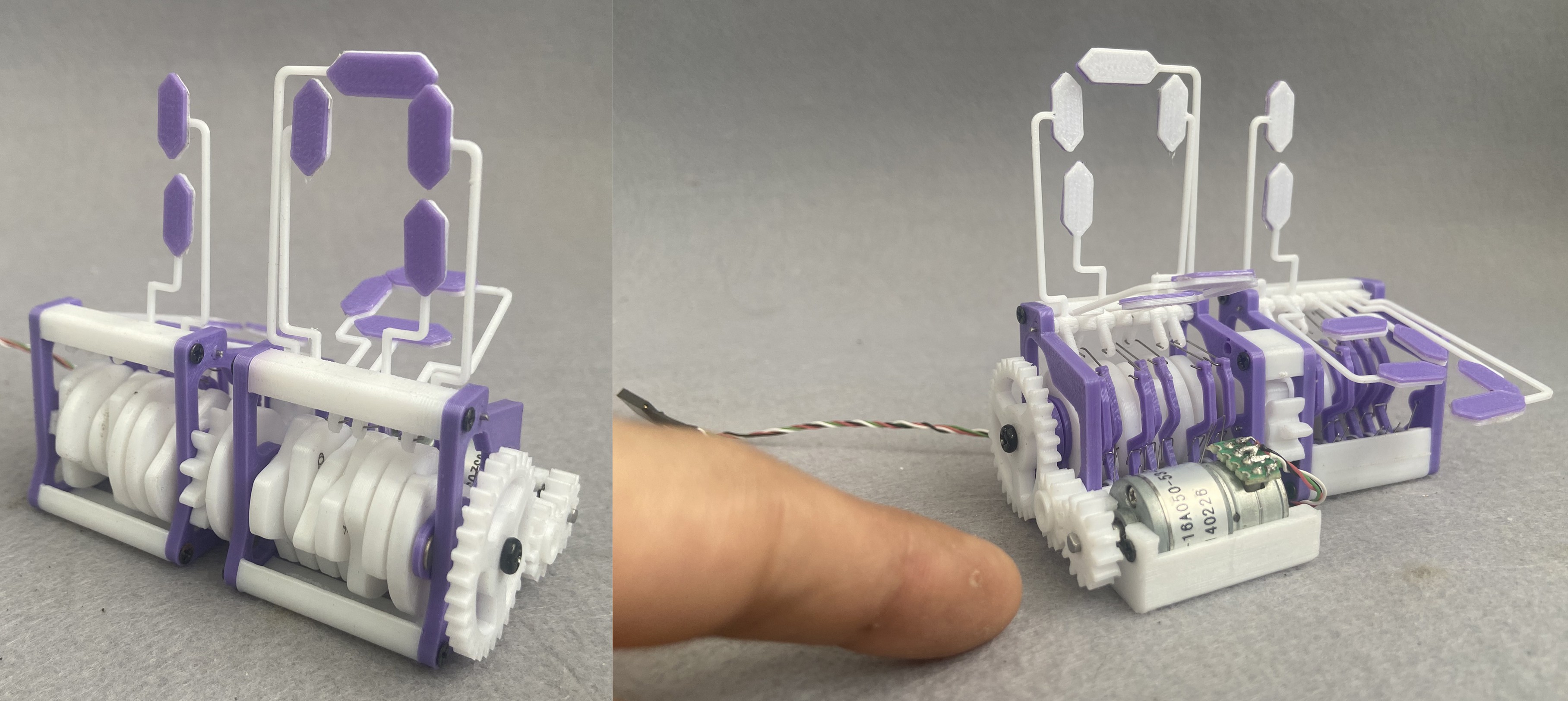
Note the scale :
Adjusting the time :


 Paul Kocyla
 core weaver
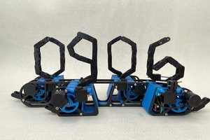
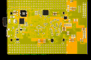
What PCB board did you use? Do you have an electrical schematic of the circuit?