ElectroBoy
Nowadays a new ESP32 MCU is in trend which is known as esp32c3. It comes with a very small form factor and with a low number of pins gives the same power of real esp32. This version is updated and has only one core CPU based on RISC V and BLE. No mean to a use 2 core tensilica @240Mhz with small projects which comes in old ESP32.
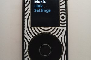
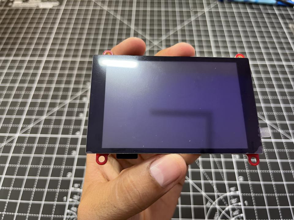
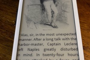
But this is not only about the microcontroller, we have a touch screen-based shield that can be used to provide better user interface. The screen comes from makerfabs open-source environment. It is 3.5 Inch SPI TFT capacitive touch screen which is way faster than any I2C screen. You can find more details regarding firmware from here.
Let’s modify some program to display own photos on this shield. This shield can be used to make a small slideshow of photos. But I am still working on playing GIF and Videos on this. As for now you can download the schematics and Gerber files of the project from the official webpage of makerfabs. You can use JLCPCB PCB prototype and SMT assembly service to make your own shield or buy from here. Sign-up now to JLCPCB and get $54 coupons as new user reward.
Features:
Controller: ESP32-C3-MINI-1-N4, 4MB Flash, RISCV-32bit, 160MHz, 400KB SRAM, Bluetooth 5
Wireless: Wi-Fi & Bluetooth 5.0
LCD: 3.5inch TFT LCD
Resolution: 480*320
LCD interface: SPI
LCD Driver: ili9488
Touch Panel: Capacitive
Touch Panel Driver: FT6236
USB: Dual USB Type-C(one for USB-to-UART and one for native USB)
Power Supply: USB Type-C 5.0V(4.0V~5.25V)
Mabee interface: 1*I2
MicroSD: Yes
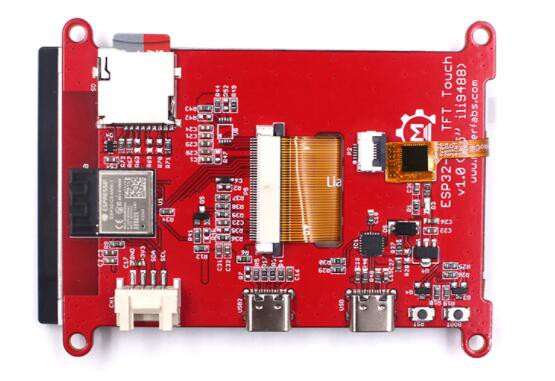
Being a number of the Makerfabs ESP Display family, this ESP32 C3 SPI 3.5-inch Touch is 320*480, with ILI9488 driver. Same as the other Makerfab's ESP32 displays, there 2 USB connectors, one for USB2UART convertor, and 1 USB native; on-board SD card, and Mabee connector(I2C) which is Seeedstudio Grove compatible, so it fits for applications that need sensor connected.
How to display your own pictures:
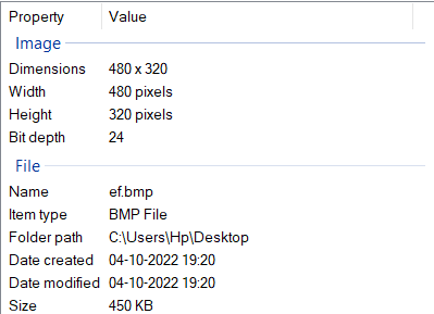
The shield comes with a SD CARD and the code the code is designed to read the SD files automatically. But only support 24-bit BMP files of 320*480 resolution. And a modification in the code is required after uploading the files into SD card.
Making of compatible files:
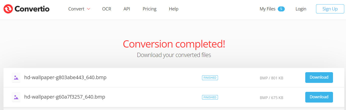
1) Download the files in JPG or PNG format that you want to display. Then open this Image to BMP convertor website. Which will convert the files into 24-bit colour format automatically. Just upload the Image files and download the BMP files from there.
2) Then set the resolution to 480*320 using the paint/ photoshop software in your laptop.
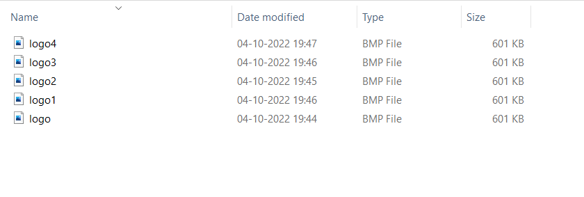
3) Upload the files into SD card and rename the files as “logo, logo1, logo2….”
Code:
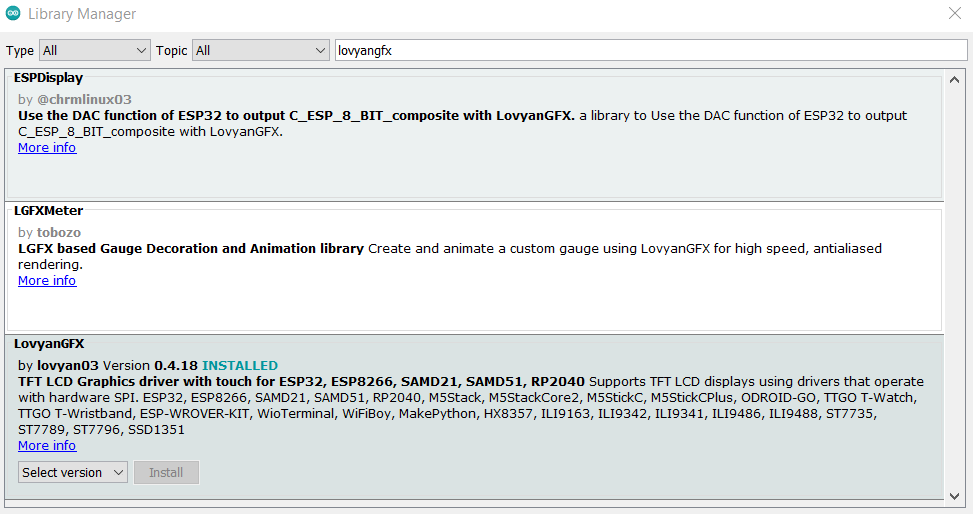
In this code some basic SD card, FS and lovyanGFX are used. You can download all these libraries from manage libraries section under tools menu. Try to get the best version of libraries from there. The code is long enough to make a mess here that’s why I am only sharing some modifying part. You can download the full code and schematics from here along with the images used by me.
i = 0;
lcd.setRotation(3);
print_img(SD, "/logo.bmp", 480, 320);
delay(1000);
print_img(SD, "/logo1.bmp", 480, 320);
delay(1000);
print_img(SD, "/logo2.bmp", 480, 320);
delay(1000);
print_img(SD, "/logo3.bmp", 480, 320);
delay(1000);
print_img(SD, "/logo4.bmp", 480, 320);
delay(1000);
In the same manner different images can be displayed. you can lower down the delay the microcontroller support up to 100FPS highest.
Uploading the code:
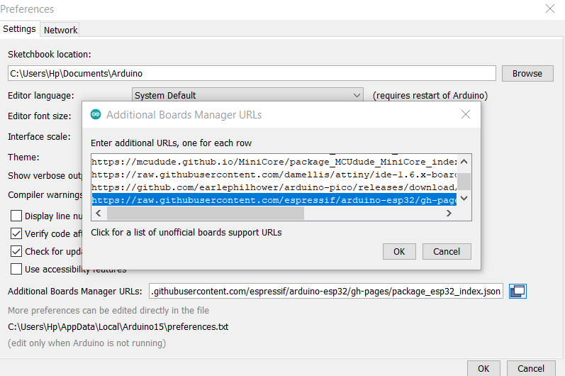
Paste this code in the preferences section under the file menu and download the latest version of esp32 boards form tools section in Arduino IDE.
https://raw.githubusercontent.com/espressif/arduino-esp32/gh-pages/package_esp32_index.json
Then select the ESP32C3 dev board and the right COM port.
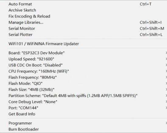
No need to change more settings and then click to upload. It will take a longer time in compiling the code for ESP32C3 than simple ESP32. Error may occur due to absent libraries.
Schematics of...
Read more »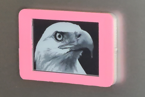
 Waldo Wolmarans
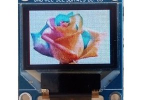
 Chris G