 Arkadi
KEY FEATURES:
- Rotary Volume Control
- Touch Based Mute/Unmute Control
- Automatic Potentiometer Position Determination and Calculation (this means that anytime the device is unplugged and plugged back into a computer the code calculates the position of the potentiometer and sets the correct corresponding volume automatically. If the device were to be plugged in and the pot set to the lowest setting the computers volume would be at its minimum. If the device were to then be unplugged and have its pot knob set to the max and then plugged back in, the onboard code would recalculate the pot position and the computers volume would be set to the max.)
- LED's which visually indicate whether volume is enabled. (Green : enabled, Red : disabled)
RP2040 Pins and Connections
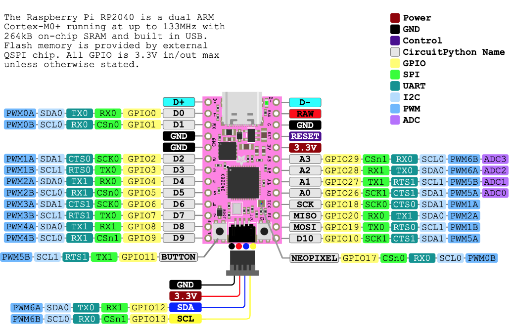
The 3.3V pin is connected to a common positive rail and the GND rail is connected to a common negative rail. This voltage is used to power both the Red/Green LED's as well as supply voltage to the potentiometer which will essentially be used as a variable voltage divider. Pin A0 is being used as the main ADC pin and is connected to the wiper terminal of the potentiometer, Pin A3 is being designated as the capacitive touch pin for touch based input, pin D8 is driving the Red LED, and pin D9 is driving the Green LED.
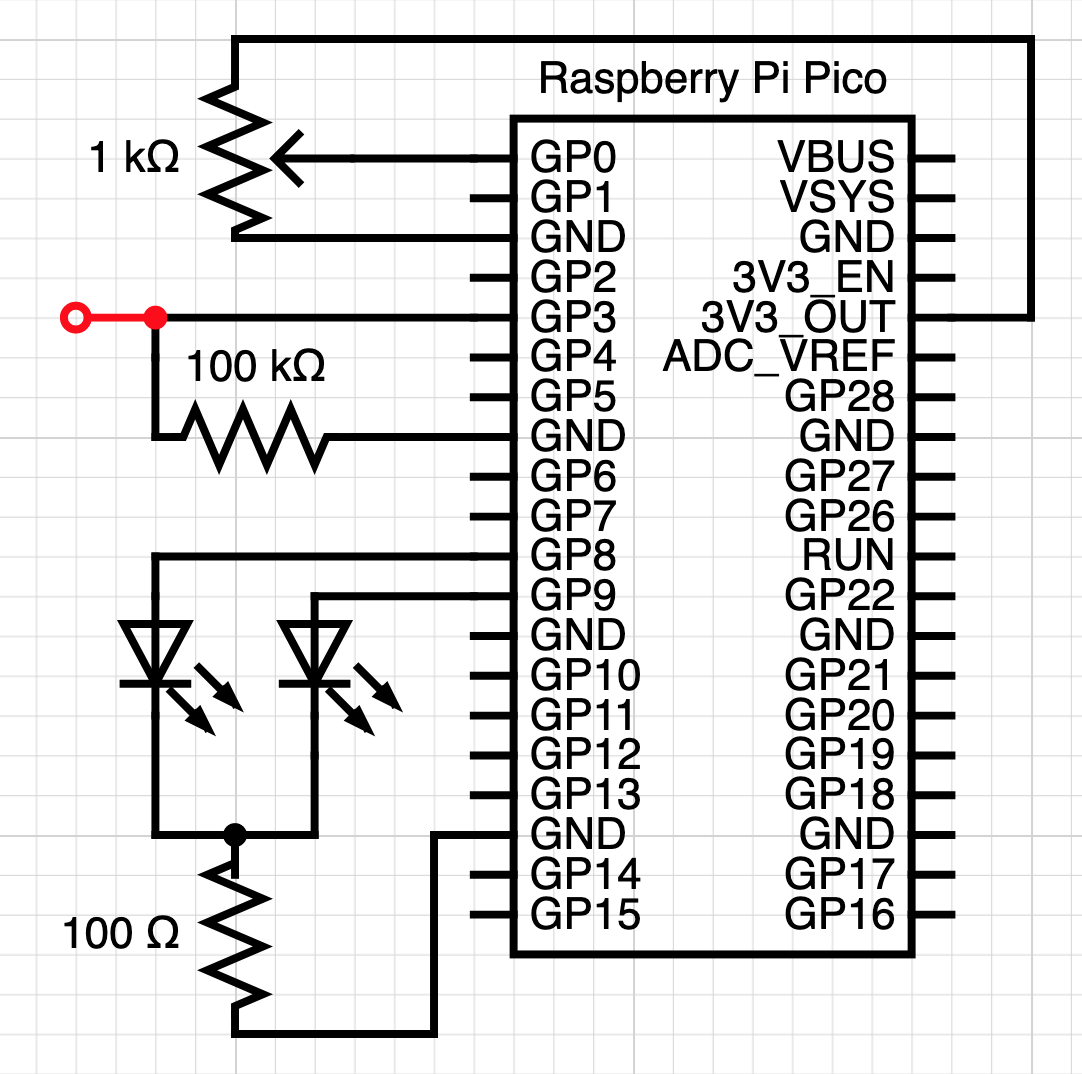
Schematic
This is the wiring diagram for the controller. While the board being used is not a Pico, the 2040 chip is the same on both boards with most of the pins overlapping. The red wire connected to GPIO pin 3 (GP3) is the capacitive touch end.
Volume Adjustment Principle of Operation and Logic Dissection
Analog and ADC Workings:
The volume control works by leveraging the potentiometer which has one terminal connected to 3.3V and the other to ground. The potentiometer has a wiper which sweeps over a resistive material which is connected from 3.3V to ground, as the wiper is moved (rotated via the knob) from the 3.3V terminal to the ground terminal, the voltage read out (output) from the wiper terminal increases to the maximum available voltage as the wiper is rotated to the ground terminal position. Voltage increases due to V=IR. If current is fixed, then an increase in resistance will lead to an increase in voltage. This effect occurs in the potentiometer since as you are rotating the wiper closer to the ground terminal, the effective length and thus resistance of the resistive material increases.
Using the onboard ADC (Analog to Digital Converter) we can convert the continuous analog voltage signal from the potentiometer into a discrete digital signal which works by sampling the signal and providing integer values in place of continuous (floating point) values. Whenever I used the ADC to read the min and max voltage output from the potentiometer [0 to 3.3V], I found that the ADC provided integer values in the region of around 0 to 64700. Since analog values are subject to change and fluctuation, the upper reading was an average of multiple readings. Since working with such large numbers is a bit unruly, I implemented a function which converts the integer values into a corresponding 0 to 3.3 range, essentially converting our data stream into a voltage representation now that the data has been taken in by the microcontroller.
def get_voltage(pin):
    # converting ADC pin values to a 0 to ~3.3V range (accuracy may vary)
    # avg ADC max is around 64700
    return (pin * 3.3) / 64700
Code and Logic:
There are 16 volume divisions for a Mac's volume parameter (17 if you include mute) as shown here in the volume icon which appears when adjusting the volume.

Since there are 16 divisions, create an array of volume boundaries which is essentially just the digitized and voltage converted max output range of the potentiometer (~3.3) divided by 16 possible volume divisions. This is accomplished by first creating an equivalent volume 'unit' for our code which is done by creating the fraction: (Max output) / (Max divisions) -> (3.3 / 16). After the unit is created, we populate the array with a for loop which runs 16 times. The for loop appends the unit fraction and after every iteration appends the unit fraction added to itself. The array is initialized with a 0 in it since it acts as the 17th, 'mute' volume division.
# creating arr of volume boundaries
volume_boundary_array = [0] # include a starting zero in the array in order to have mute option
vol_fraction = round((MAX_VOLTAGE / MAC_TOTAL_VOLUME_DIVISIONS), 1)
sum = vol_fraction
for i in range(MAC_TOTAL_VOLUME_DIVISIONS):
    volume_boundary_array.append(sum)
    sum += vol_fraction
The array elements can be described with sigma notation:
Once the array is filled with these boundaries, constantly read the current potentiometer output and use a function which compares the potentiometer output with the boundaries in the array. You can think of this as creating a gauge pointer. However, since our potentiometer data is unlikely to correspond exactly to a value in the volume boundary array, we numerically buffer (or pad) our current position by adding and subtracting the numerical buffer which effectively 'widens' our gauge pointer and makes finding your relative position in the array easier.
The code is initialized by first determining the pot position and setting your current index position relative to the boundary array. Once initialized, the code enters a while loop finds the index position of the nearest element in the array and if your cursor overlaps or is near an element in the array then the index position is returned and is set as the current position.
def find_nearest_boundary(current_volt_val, error):
    for idx, array_val in enumerate(volume_boundary_array):
        if (array_val - error) <= current_volt_val and current_volt_val <= (array_val + error):
            return idx
If the current index position is greater than the last index position, then the volume is incremented. If the current index position is less than the last index position, then the volume is decremented. Only if the current position is greater than or less than the last position will the volume be incremented and return True, which allows for the last position to be set to the current position. By using strict inequalities we avoid any problems if our cursor remains on a boundary value and only update our last index position with the current position if a boundary is truly crossed relative to our last position.
def up_or_down_determiner(current_position, last_position):
    # volume up
    if current_position > last_position:
        cc.send(ConsumerControlCode.VOLUME_INCREMENT)
        return True

    # volume down
    elif current_position < last_position:
        cc.send(ConsumerControlCode.VOLUME_DECREMENT)
        return True
Visualization of what the code is doing:
The array of volume boundaries with an example of the actual current position (pointer gauge), and the padded form of the position which allows for easier registering of pot position and determination of whether or not a boundary was crossed.
