 lion mclionhead
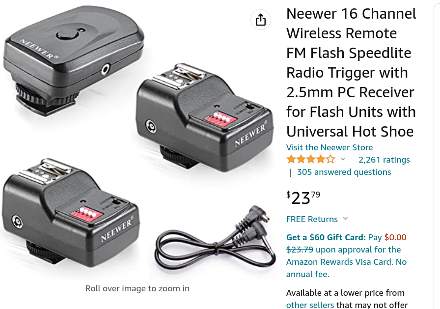
Cheap flash radio sets are manual only & very unreliable.
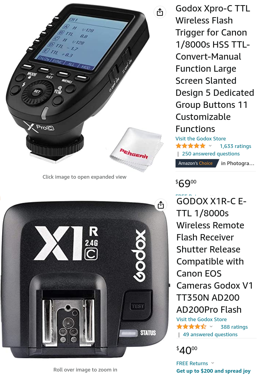
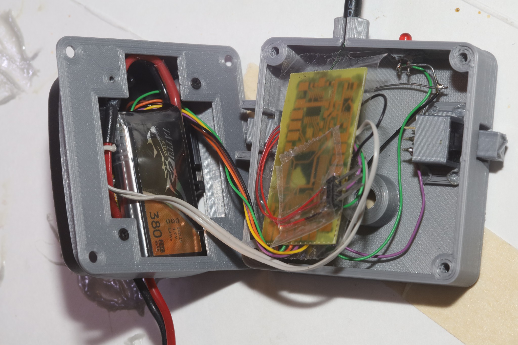
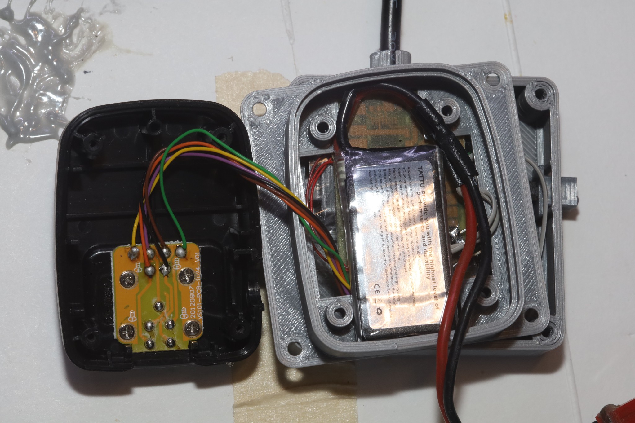
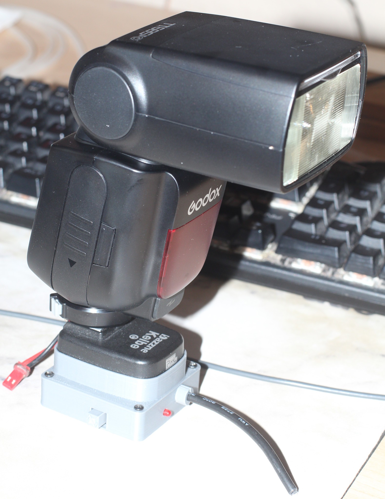
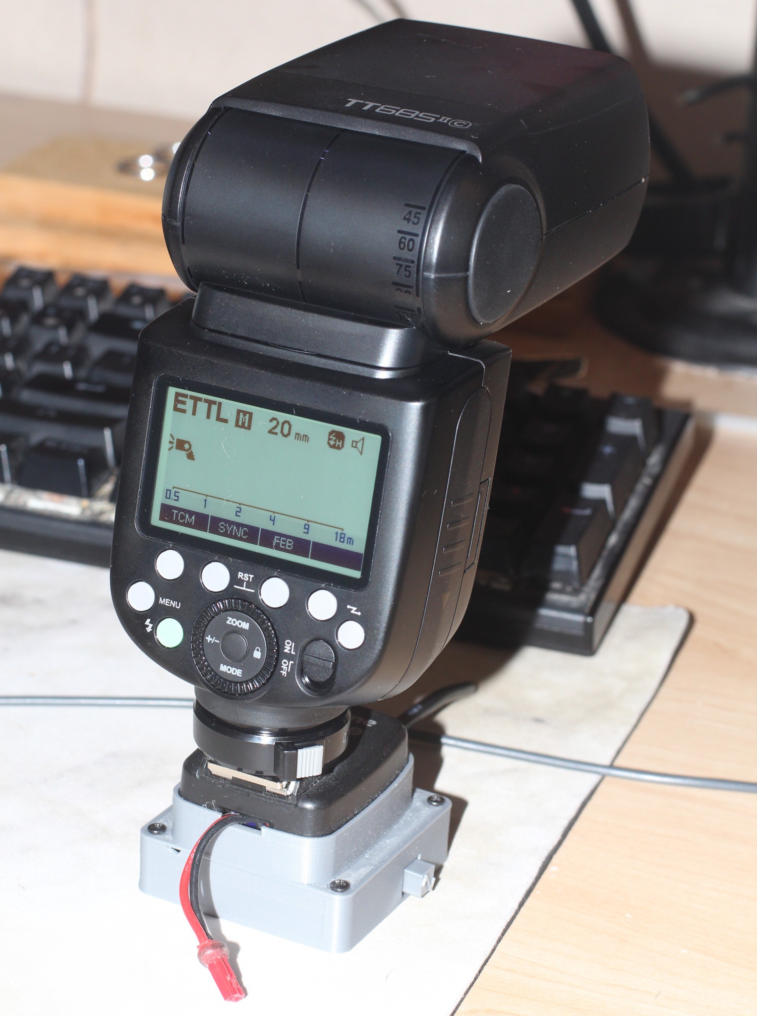
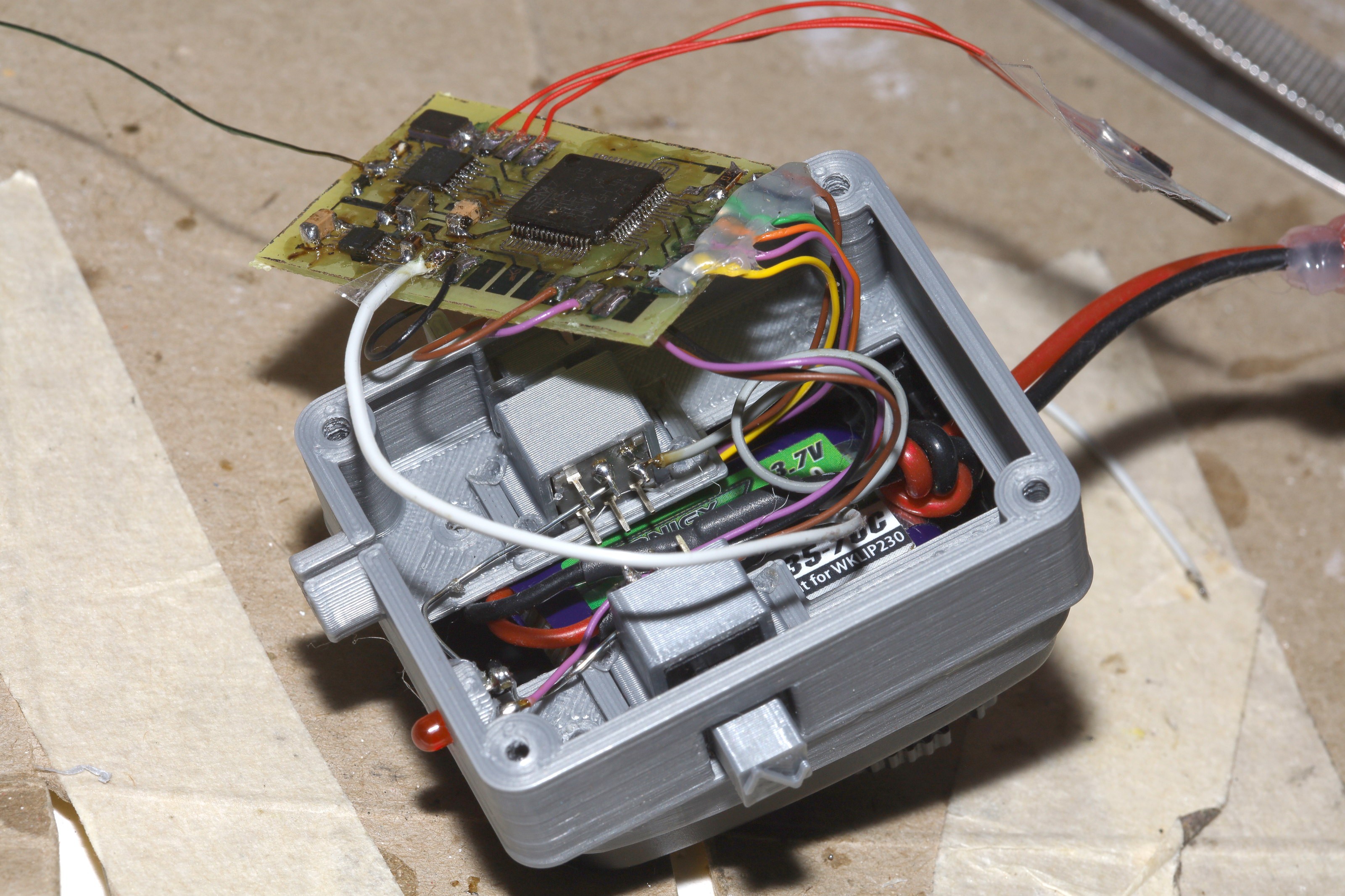
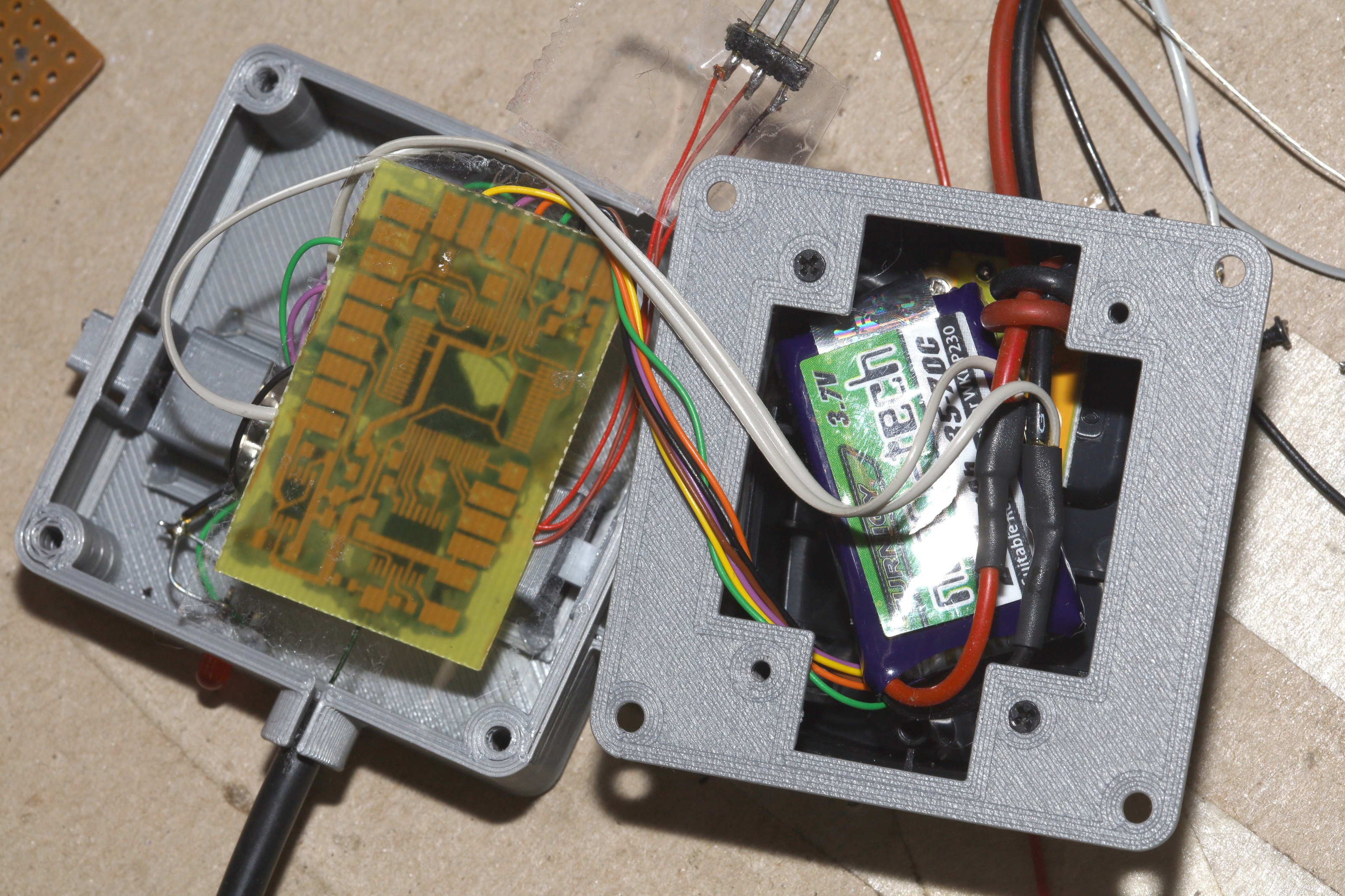
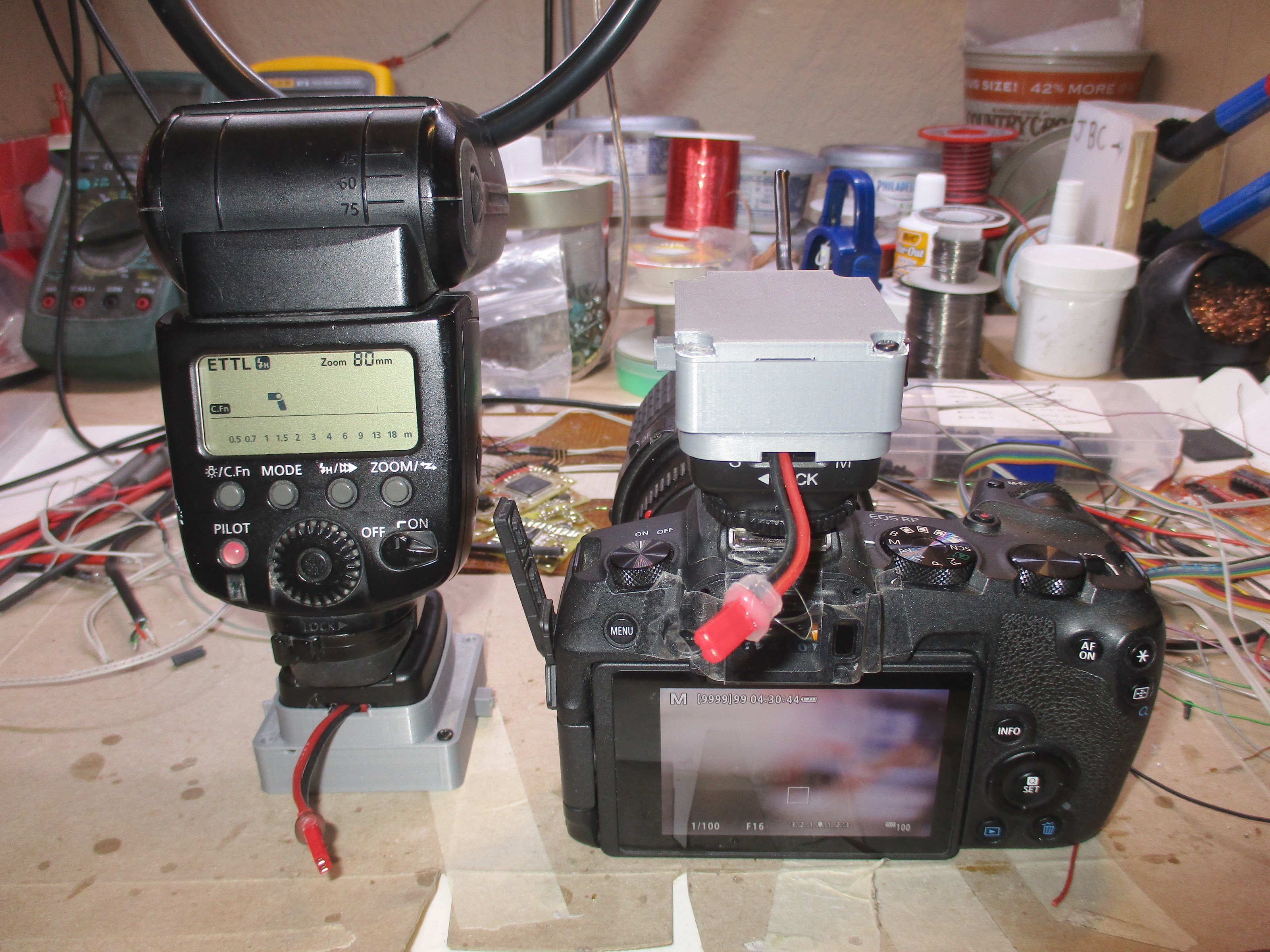
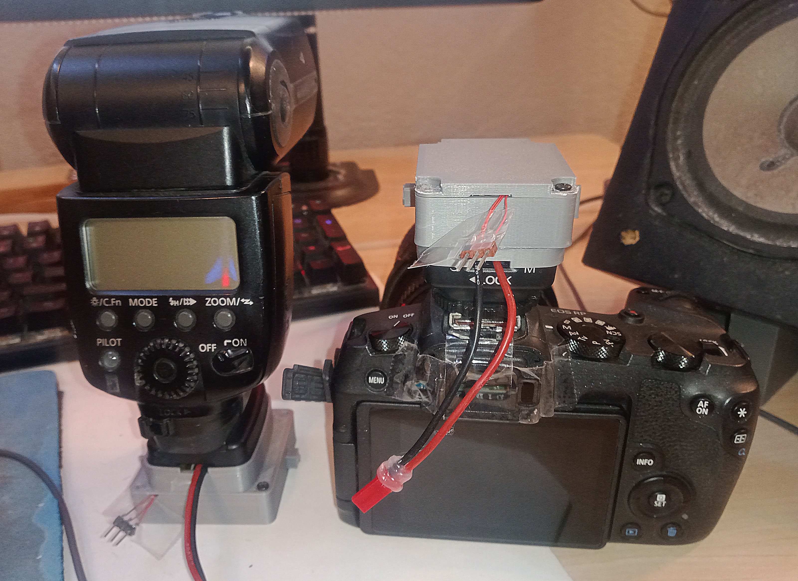
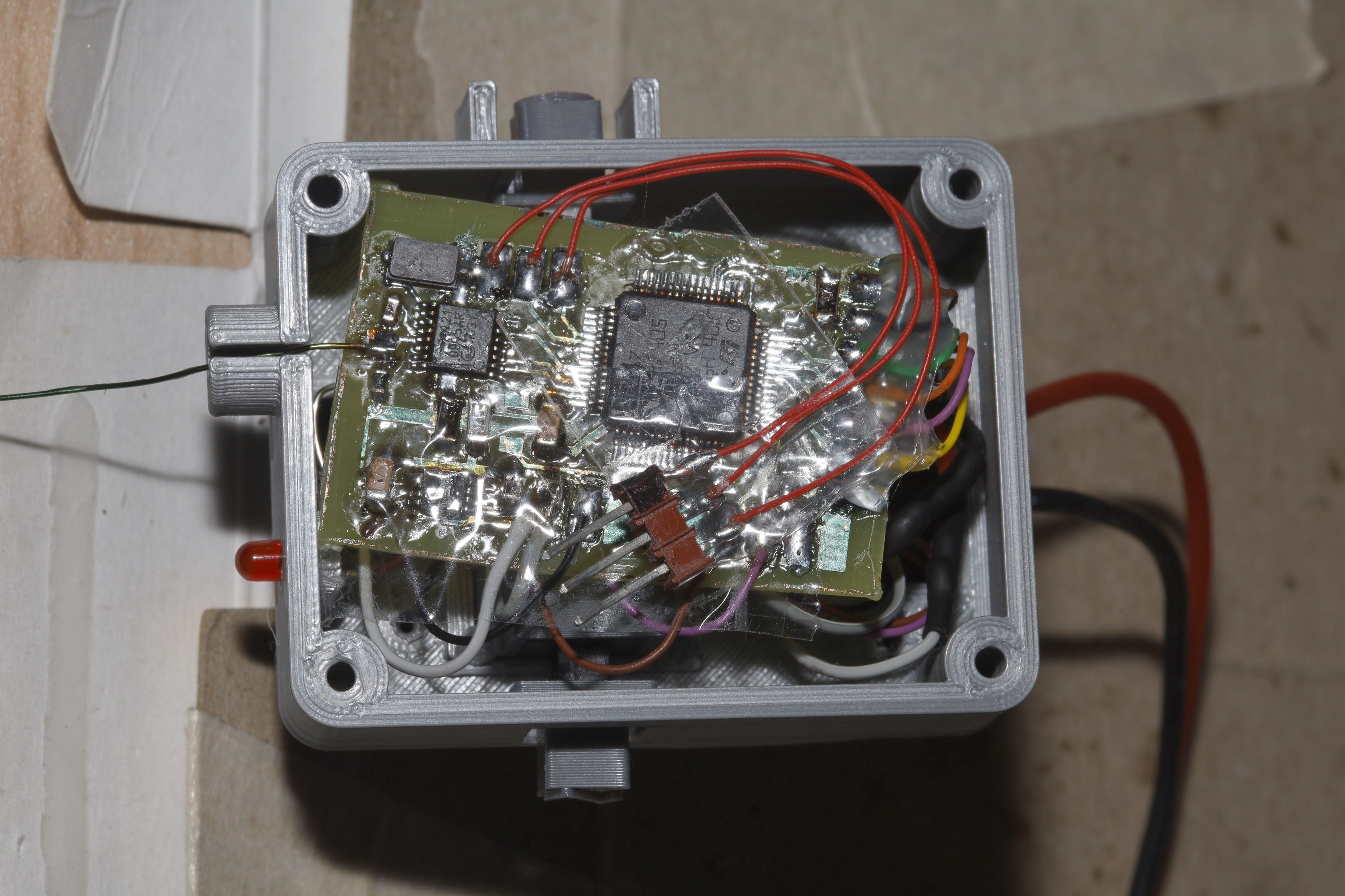
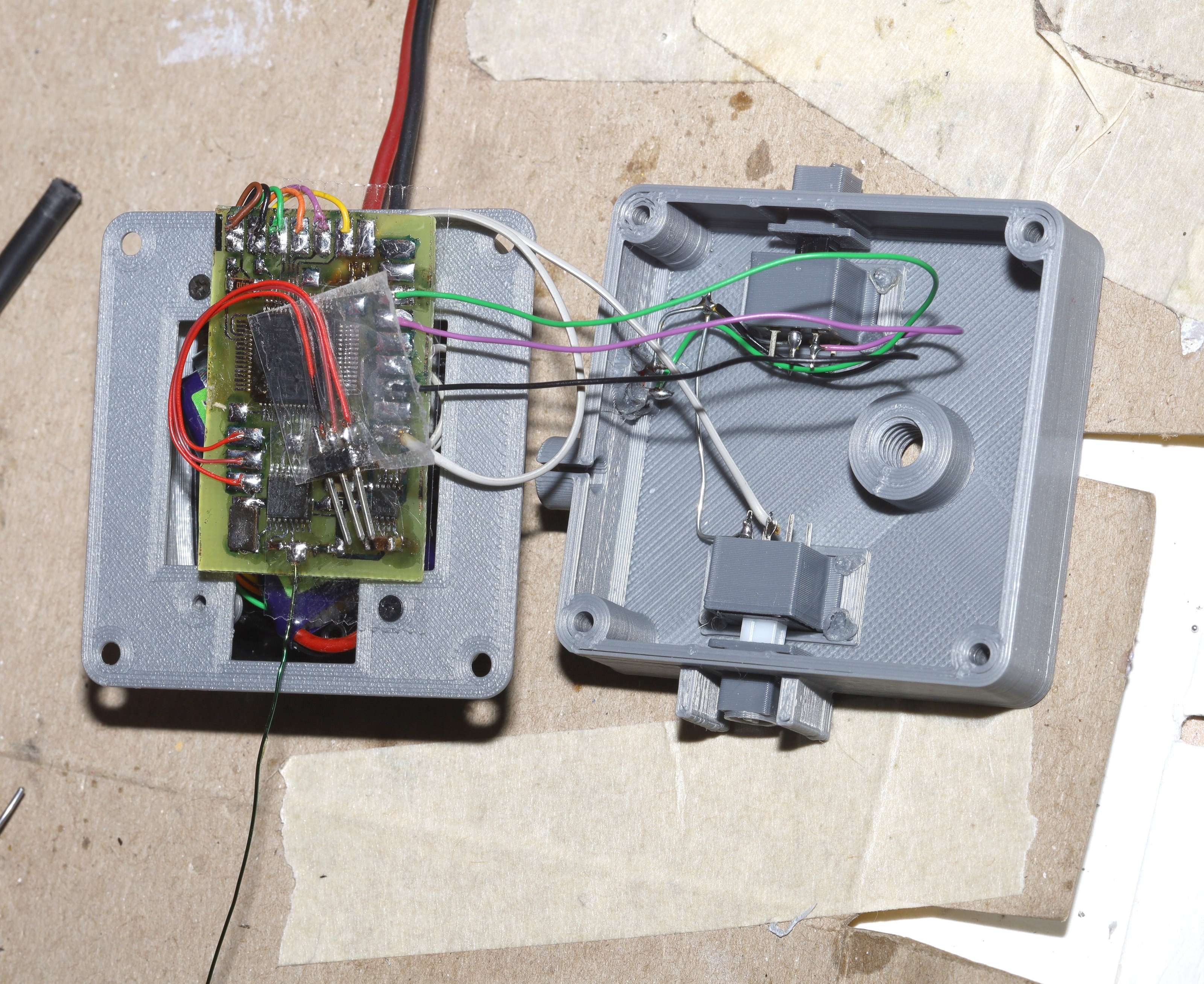
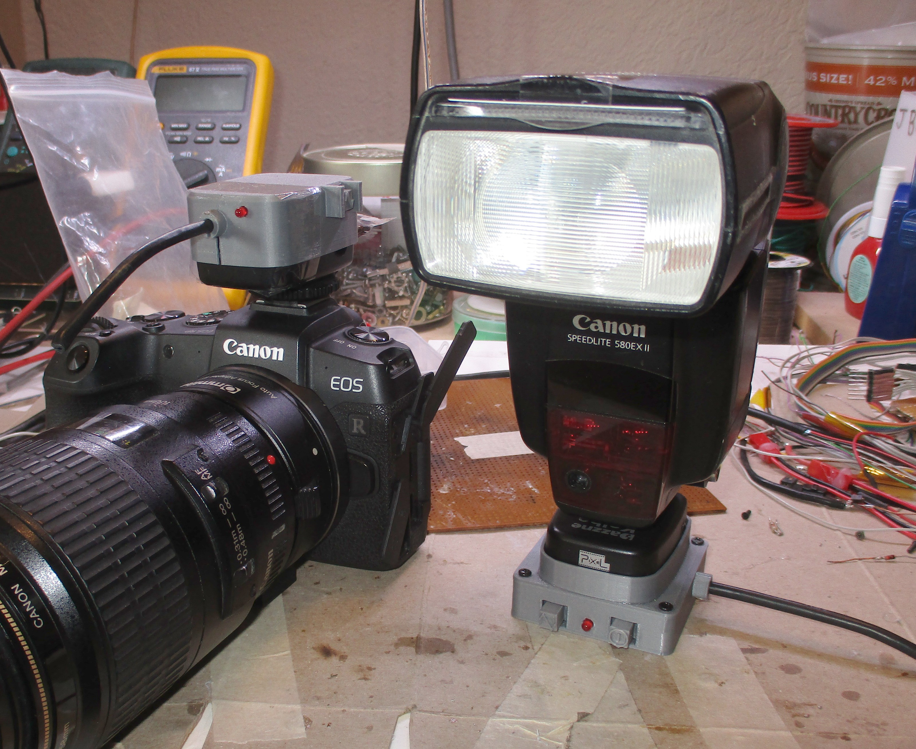
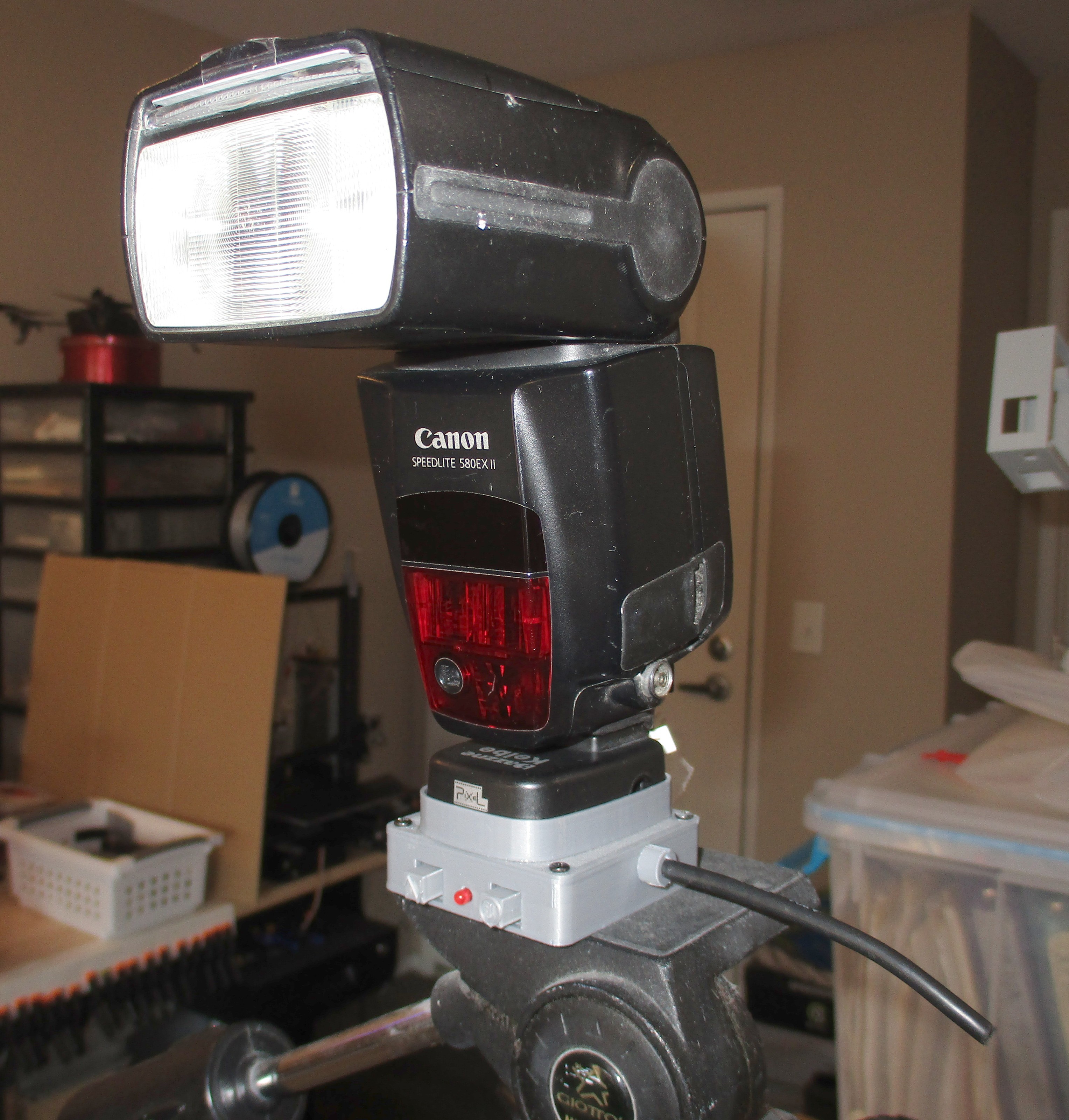
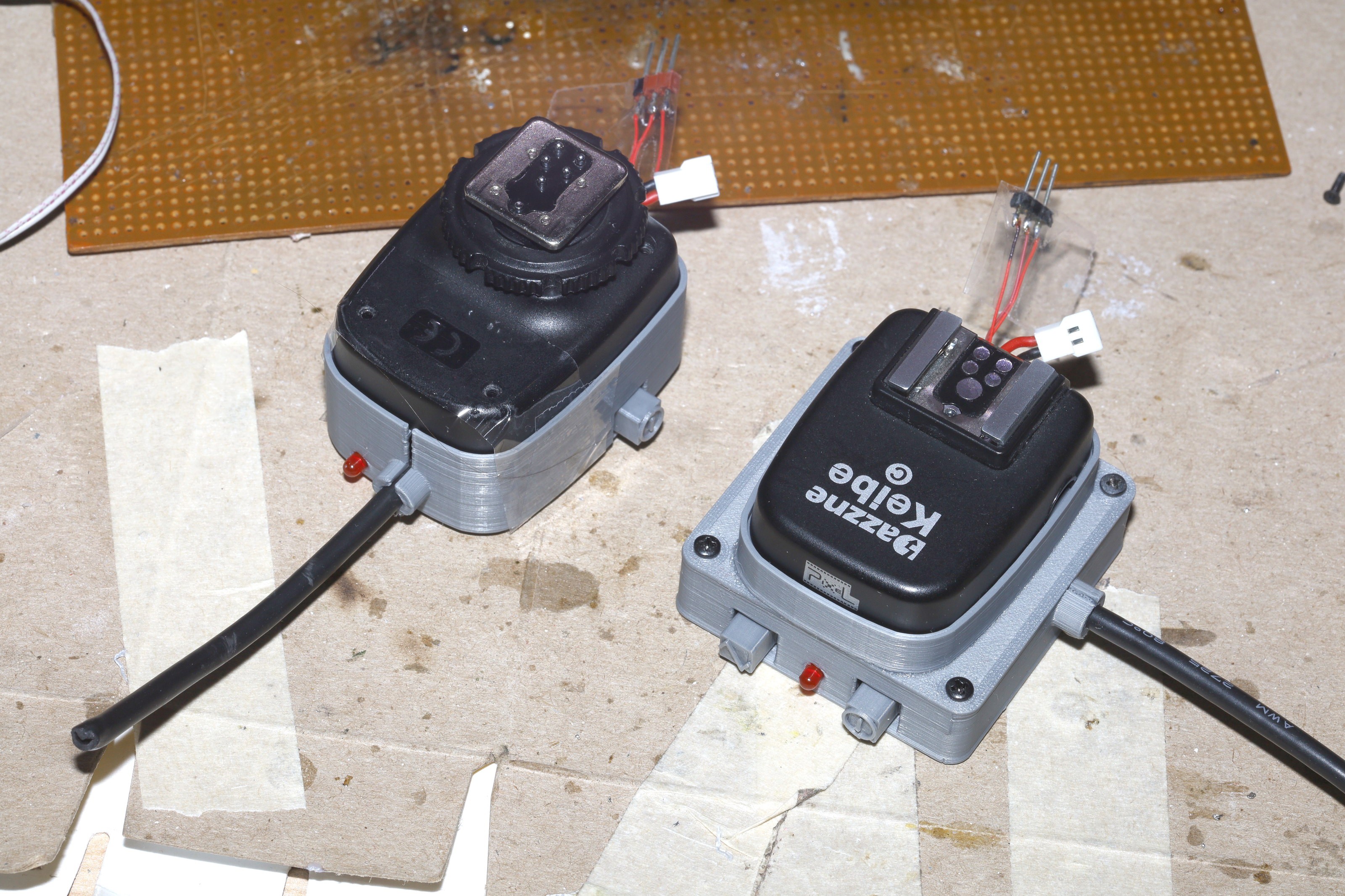
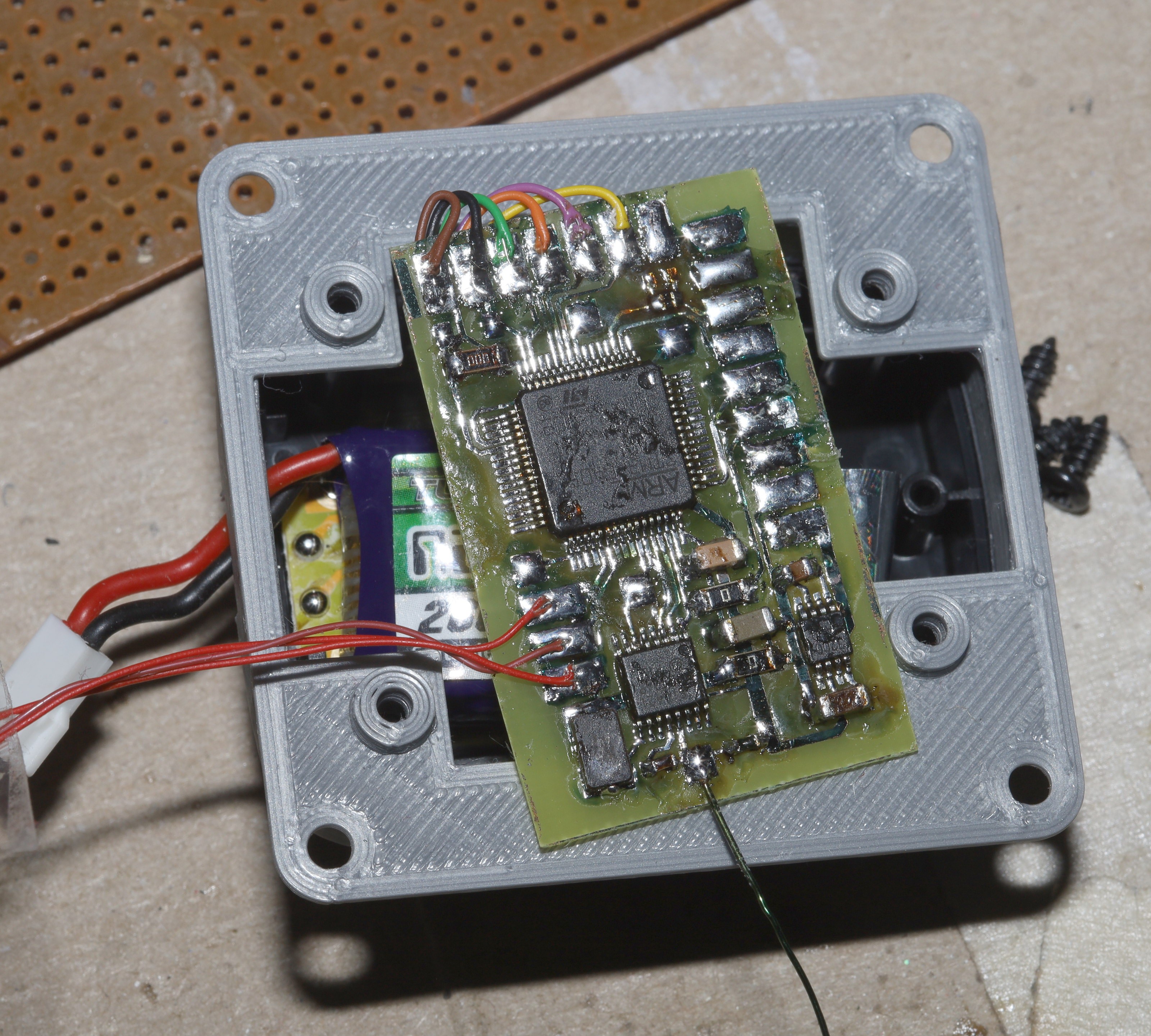
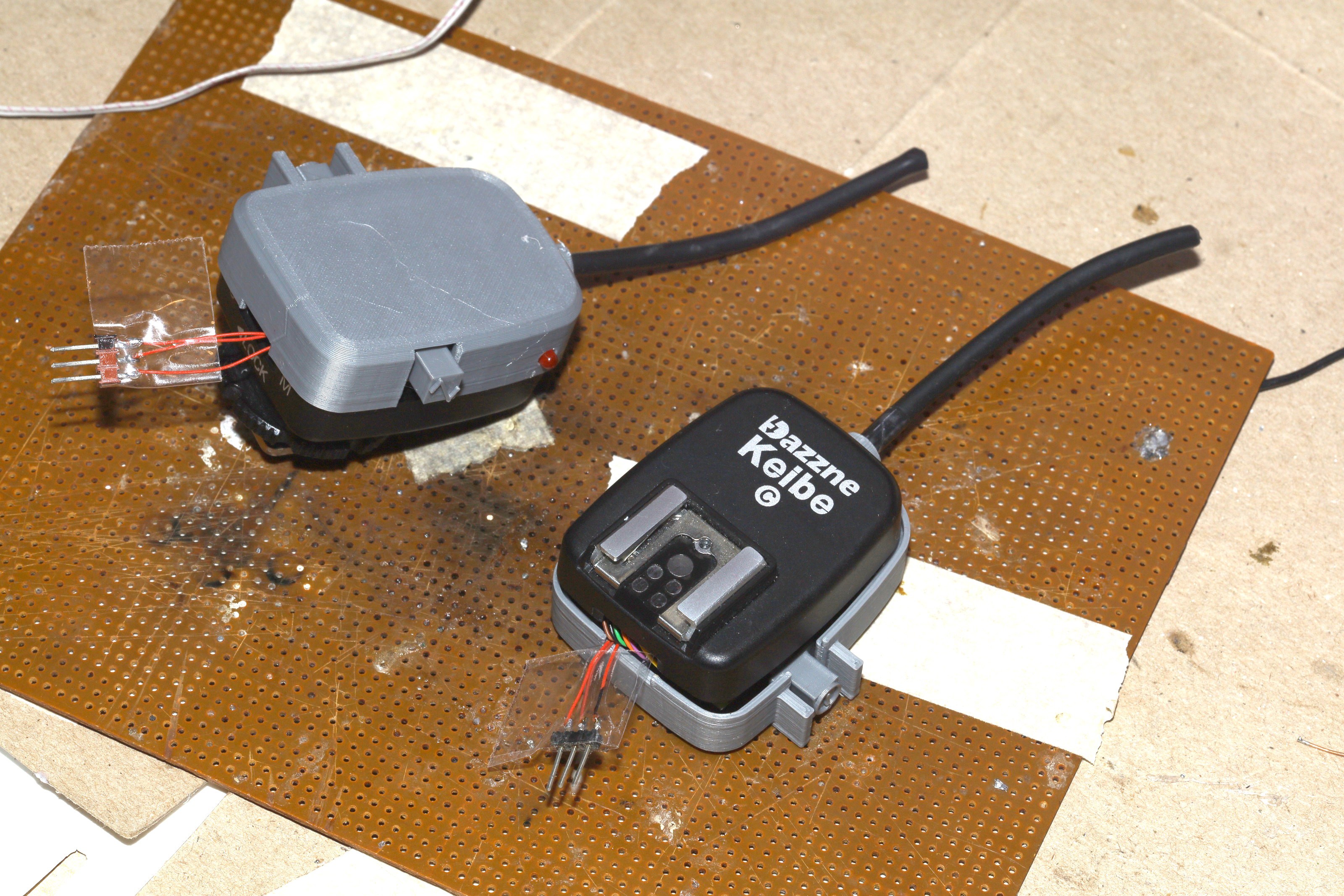
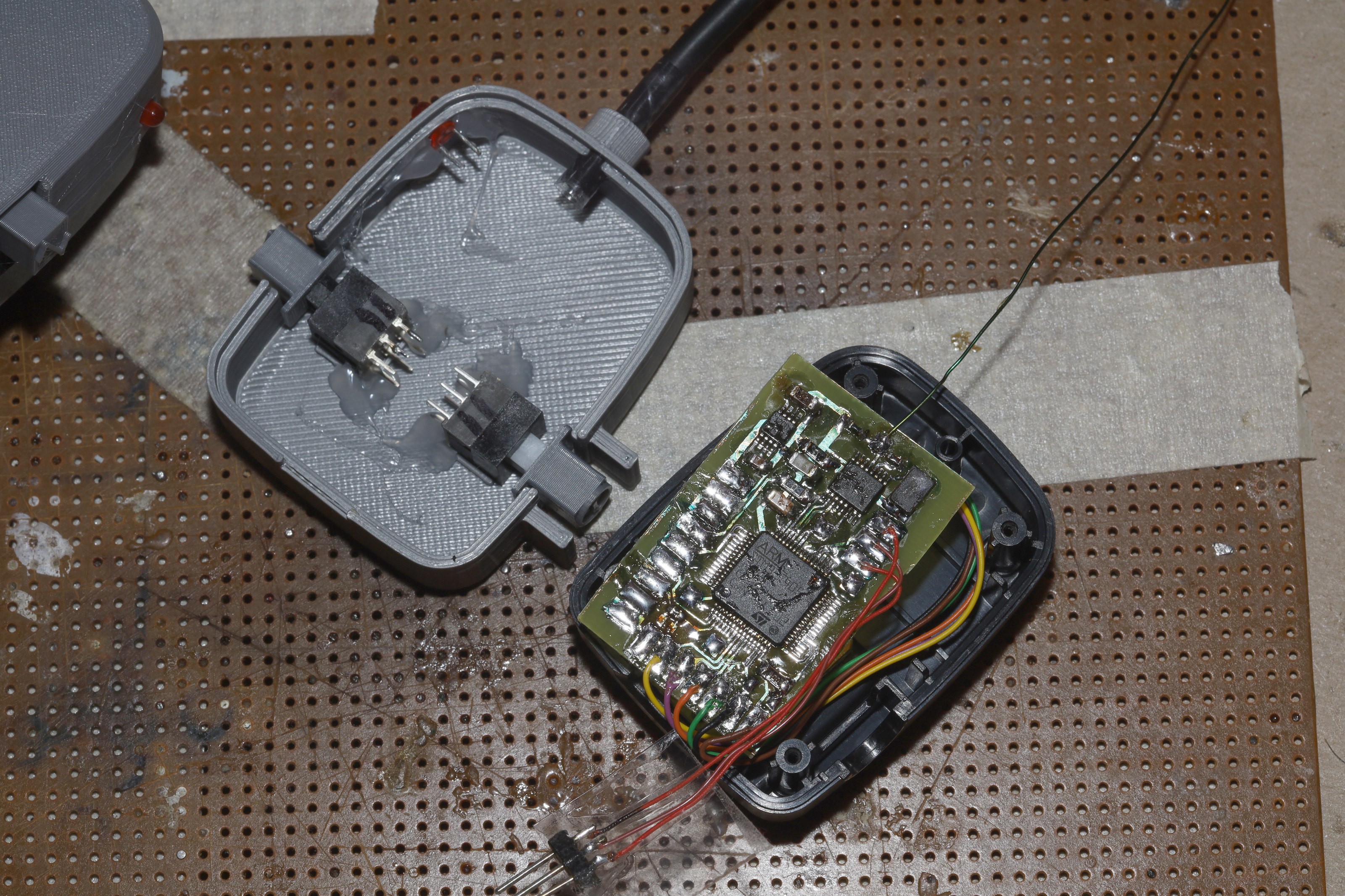
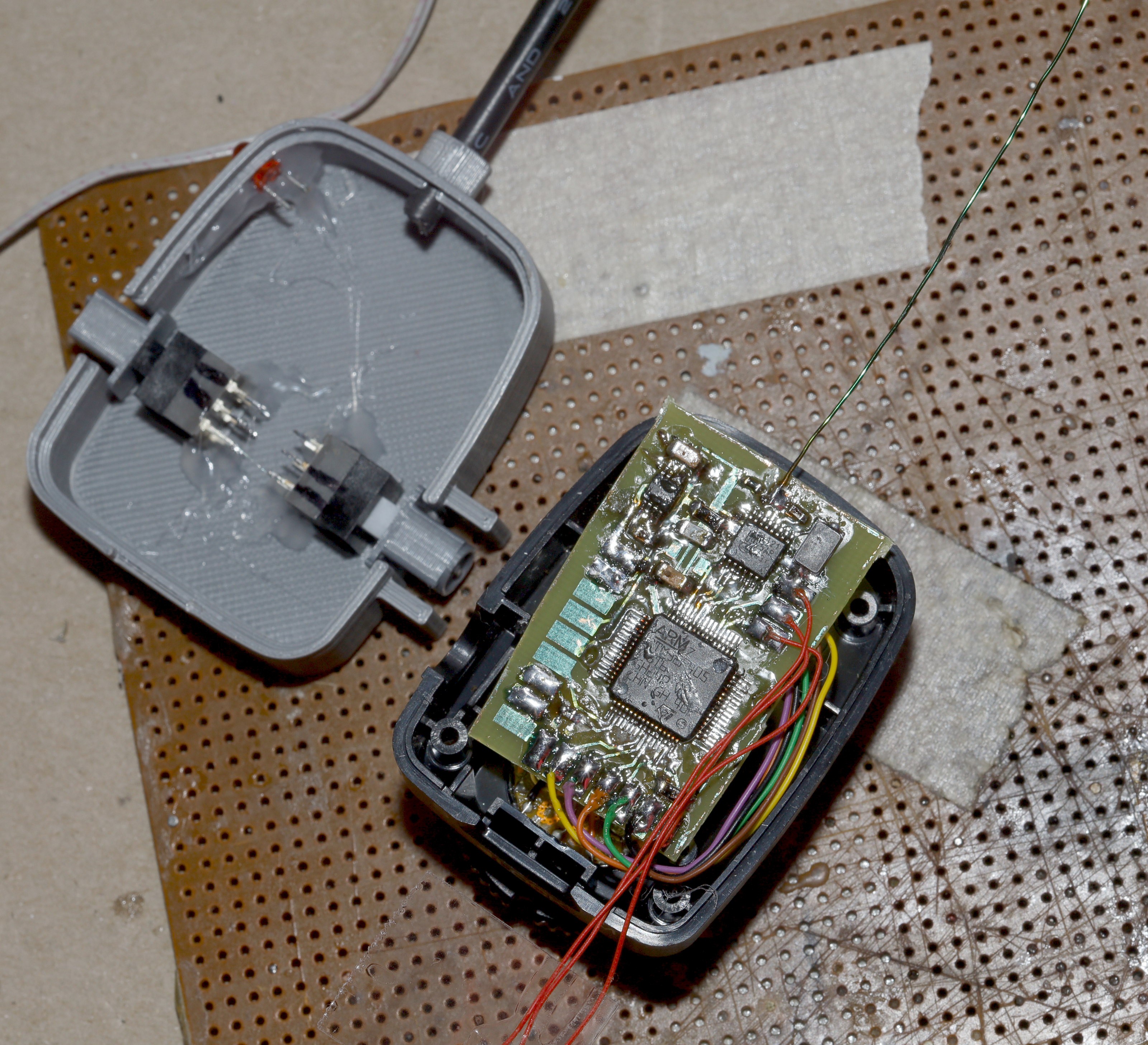
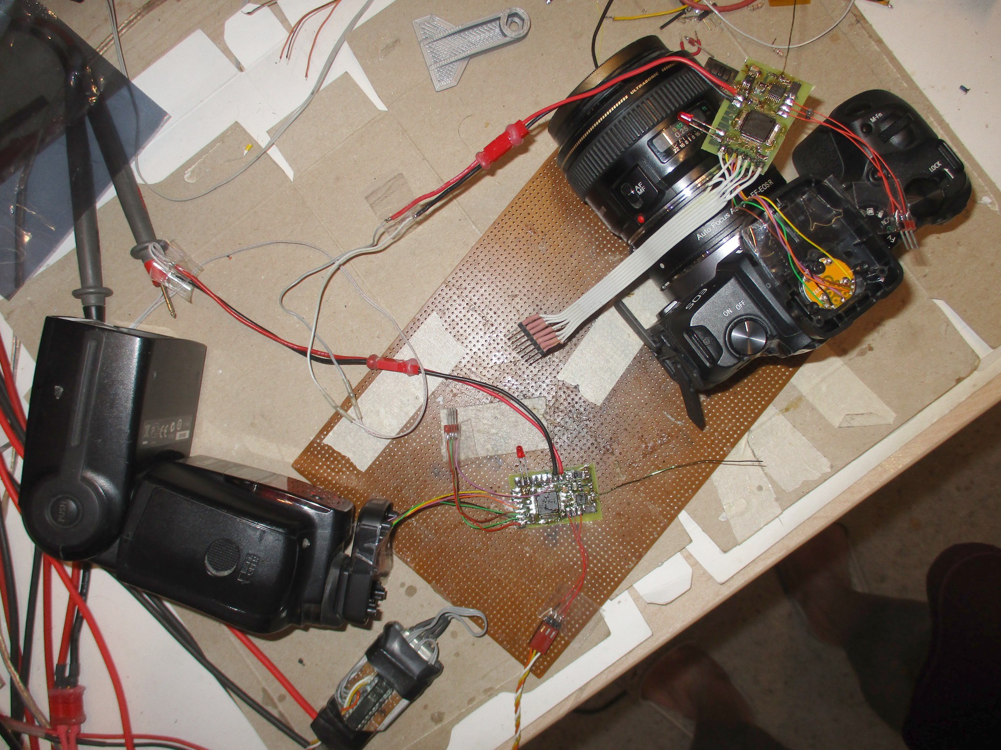
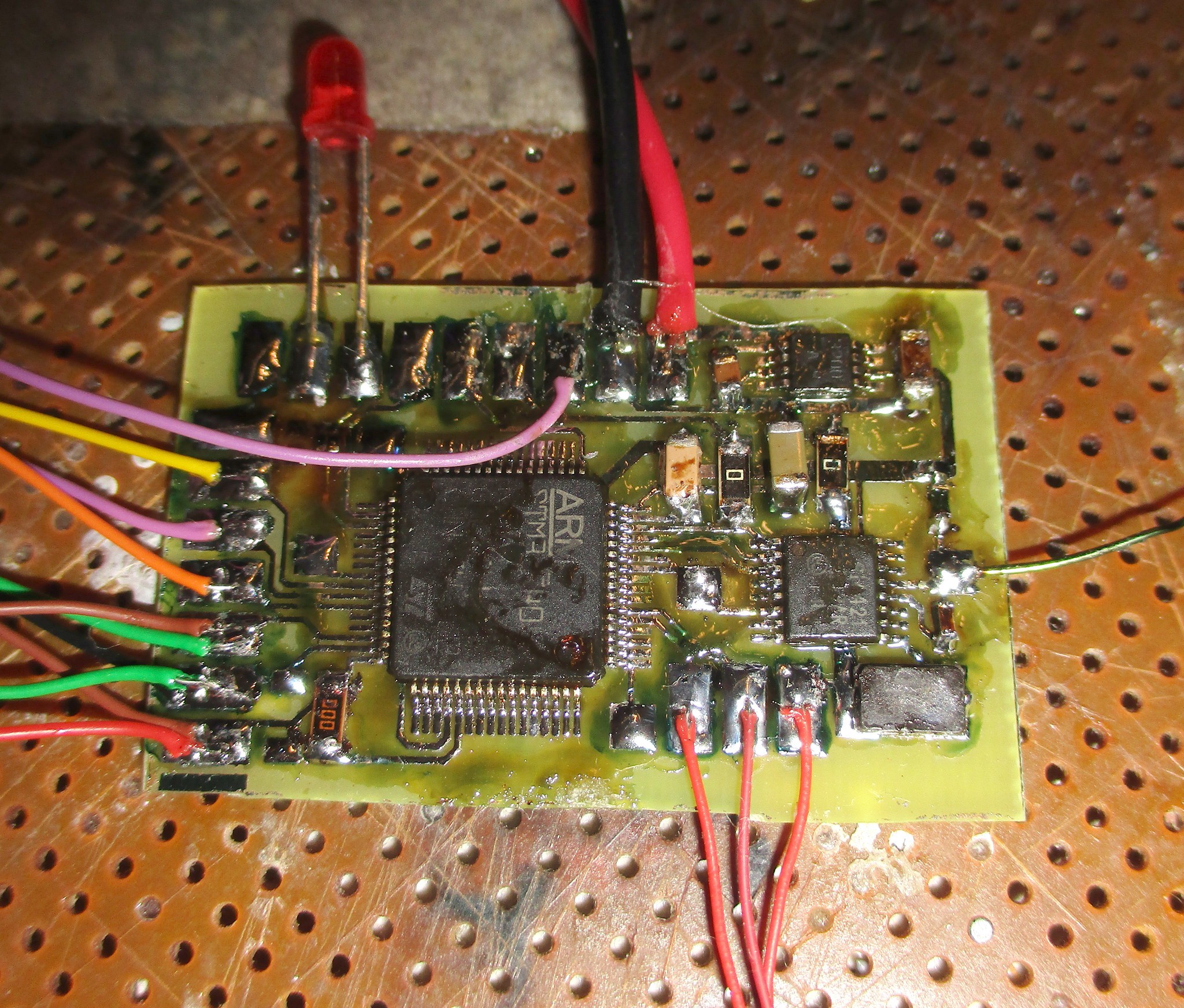
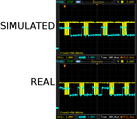
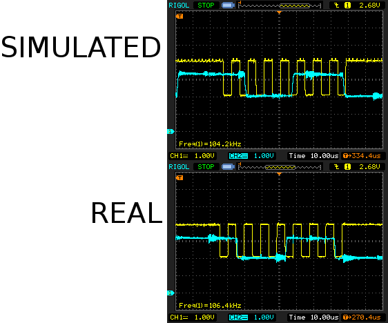
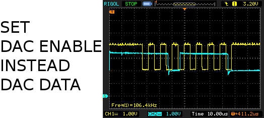
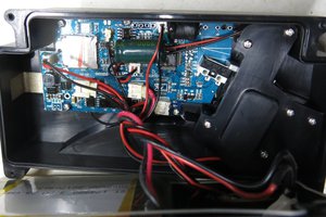
True wireless ETTL starts with a $110 Godox radio set. The decision was made to try to do it with spare parts & save 1 day of rent. Wireless ETTL is actually a difficult problem. You can't sample all 5 pins & send it over the air. It would take many megabits & microsecond latency. The workaround is to simulate a flash connected to the camera & simulate a camera connected to the flash. Between the 2, there's an abstraction of the pin signals. The trick is implementing enough of the ETTL protocol to simulate the gadgets, error protection & precise timing.
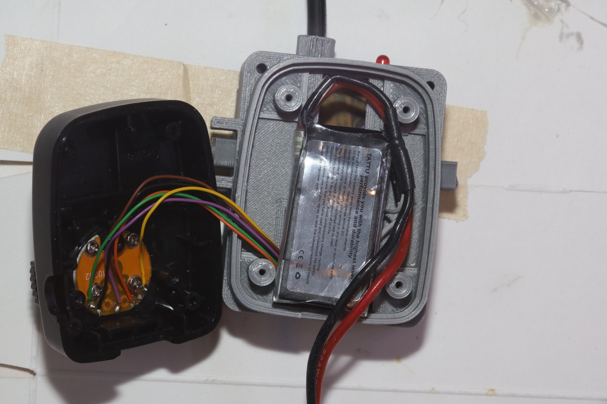
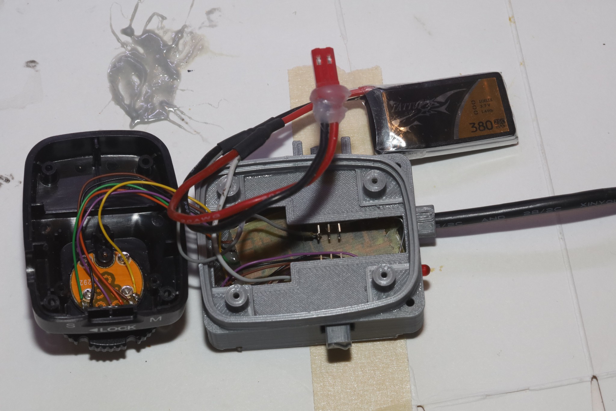
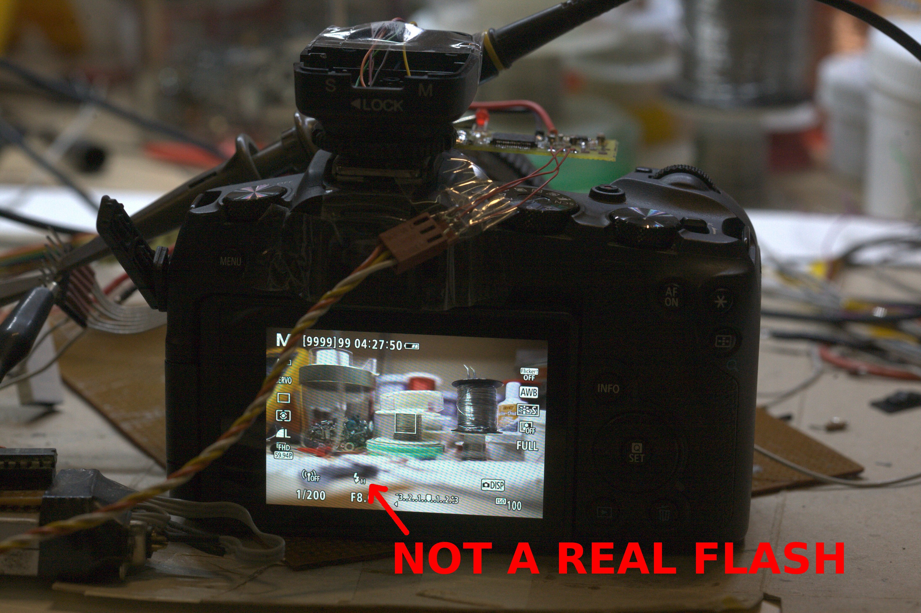
This can form the basis of converting any manual flash to full ETTL.

 maurizio.butti
 Muth
Muth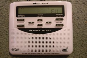
 Signals Everywhere/KR0SIV