 lion mclionhead
So 1 of the boards had a short between X & ID that managed to scrape by the initial day of testing. With it cleared, the flash worked perfectly with the signals in bypass mode. The flash interface accepted button presses & the camera didn't lock up. Running the boards on 3.3V or 5V made no difference so hope resumed for a digital 3.3V interface.
Anyways, the decision was made to try to capture data. Data moves at 100kbaud but CLK toggles at 200khz. There's no rising edge detection on the PIC comparator. It fires an interrupt for every change. The comparator seems to get behind. Trying to do it in C was too slow.
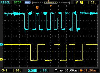
Rising edges were pictured by a toggling of 1. Polling was faster than interrupts, but still too slow to do anything. It would have to read comparator 2 to read a data pin & then write a data pin. Maybe a tight assembly loop could catch a single byte at a time before processing the data in the 50us between bytes. It couldn't print anything because a single UART byte takes 100us. The trick is catching the start of the byte. It would have to spend its life in an assembly loop polling all 5 signals & only do any processing after the 8th bit.
The other question is if the camera & flash detect the presence of each other by a non zero voltage on the data pins, that's why digital 0 is 2V. It really needs an STM32 with 2 DACs for CLK, data out & 2 ADCs for CLK, data in. Analog capture of X, ID, & data out is only needed for debugging. X & ID can go to 0V. There could be a debugging mode with taps of all the signals going to ADCs. The DACs avoid the need for op amps. This bigger board would go vertically on the hot shoe.
The beloved single wire bootloader goes in the scrap heap.
Discussions
Become a Hackaday.io Member
Create an account to leave a comment. Already have an account? Log In.