 Dan Julio
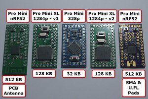
gCore uses the ESP32-WROVER-E module which has dual-CPU revision 3 ESP32 silicon, 16 MB Flash memory and 8 MB PSRAM.
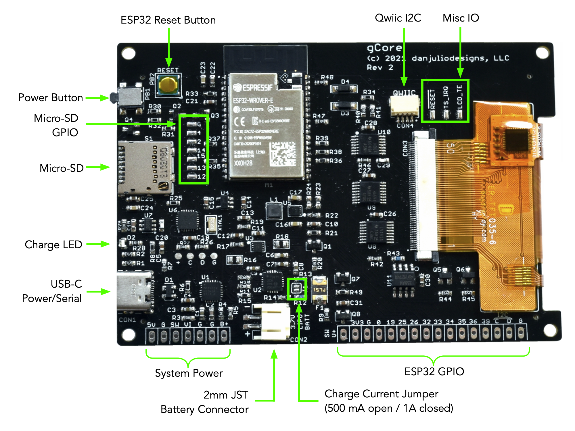
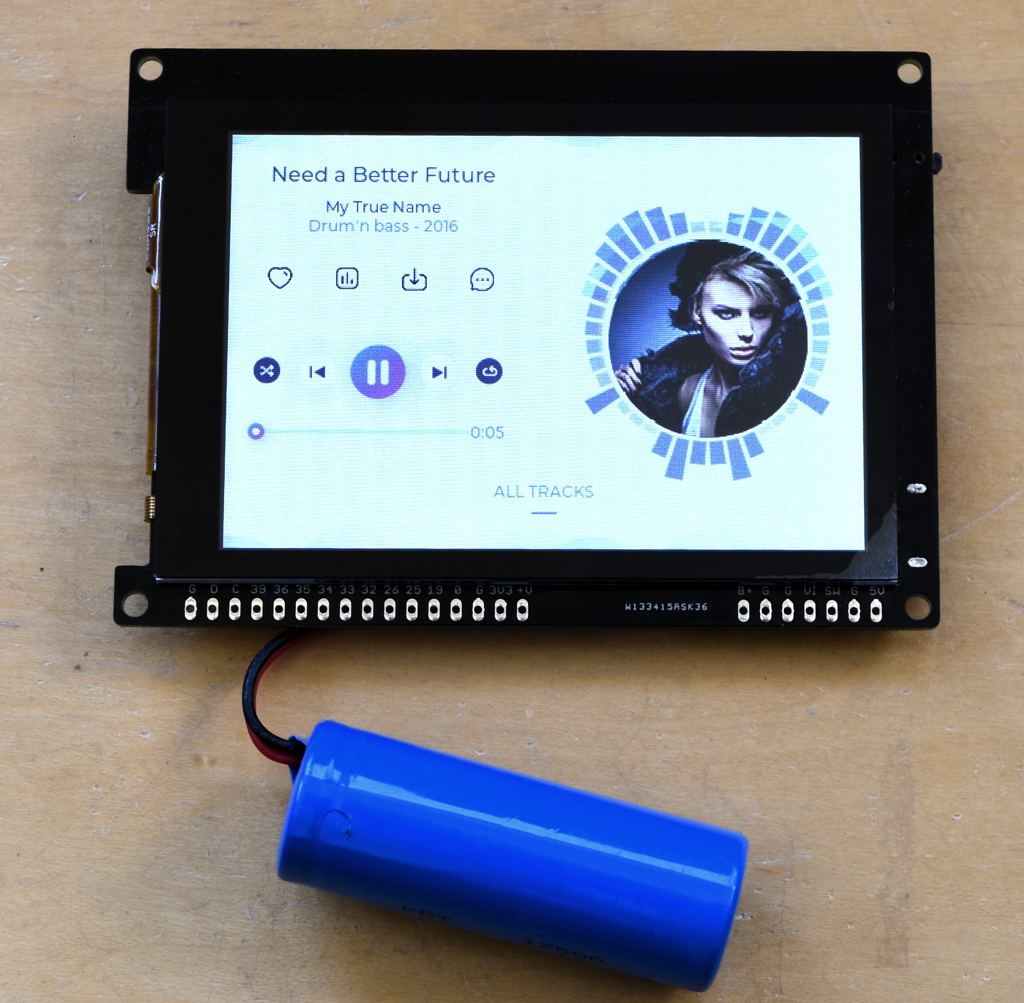
High Performance LCD Capacitive Touchscreen Display
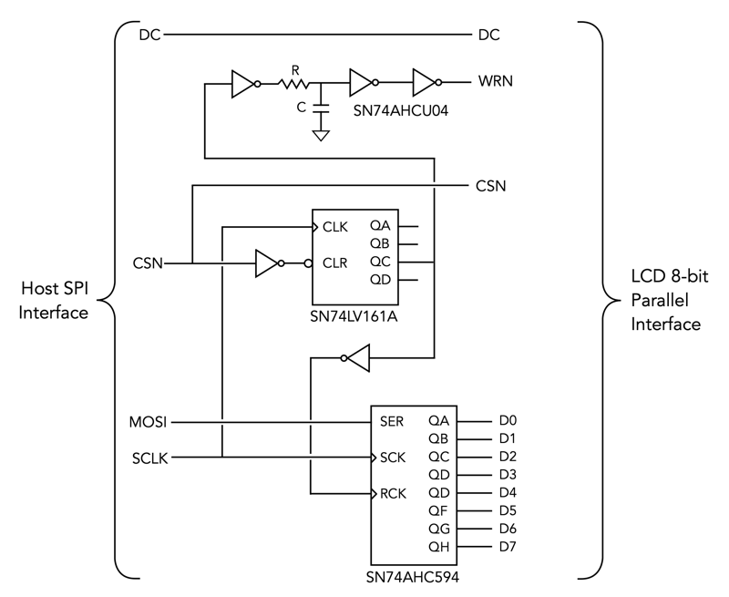
TFT 480x320 pixel LCD Display using ILI9488 controller configured to use a 8-bit parallel interface. The parallel interface is driven by a shift register and other logic connected to the native ESP32 VSPI GPIO pins. This allows code on the ESP32 to drive the SPI bus at the maximum 80 MHz (faster than the ILI9488 allows in SPI mode). Bodmer's fantastic TFT_eSPI library has been ported and screams on gCore. A FT6236 touchscreen controller allows up to two point touch detection.
Full Power Path Li-Ion Charger
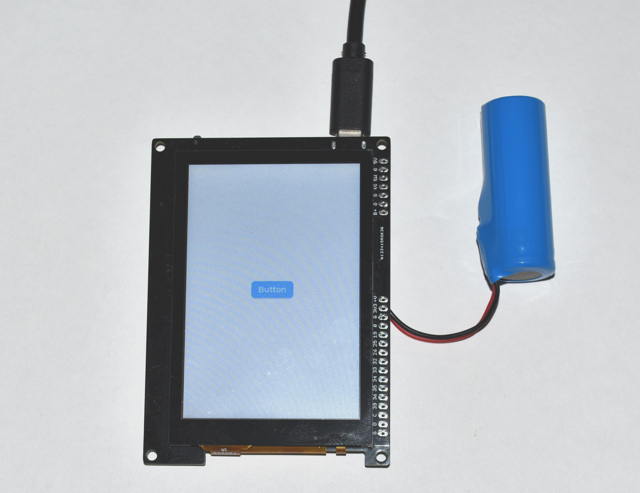
gCore is powered by a 3.7V Li-Ion or LiPo battery (typ 500-4400 mA) or USB. The battery connection uses the standard Adafruit/Sparkfun JST connector. A Microchip MCP73871 charge controller provides a separate path for battery charging and for board power. This ensures it can accurately determine charge completion and allow board power to be sourced from USB only when possible or shared between USB and battery power when necessary. I wanted a full power path charging circuit because I've seen battery life problems with the dev boards that simply hang the board load directly on the battery connection with the both powered by the same charge controller output. A jumper allows either a 500 mA or 1A maximum charge current selection.
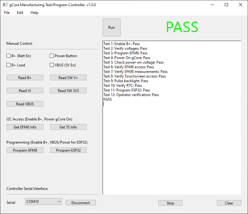
Soft Power Control / RTC
gCore contains a Silicon Labs EFM8SB20F32 8-bit microcontroller that acts as a power manager (PMIC), provides a real-time clock (RTC) with alarm and NVRAM/NVFlash, and board control/monitoring control. The ESP32 communicates with it over I2C.
- The board can be powered on by a press on the power button, an alarm from the RTC or when charging is started or completed. When powered the button has two functions. It can act as a general purpose button with presses detectable by code running on the ESP32 or it can be held for five seconds to power off the board (like the long press on laptop power buttons).
- Code running on the ESP32 can initiate a power off. The EFM8 also switches power off for a critically low battery automatically (a warning status is available to the ESP32 before power is shut off).
- Dimmable backlight control. 8-bit PWM dimming at 25 kHz.
- The EFM8 provides 4096 bytes of NVRAM and 1024 bytes of flash accessible by the ESP32 via I2C for storing parameters when the ESP32 is powered off.
- The EFM8 monitors battery voltage, load current, USB voltage and charge current. It provides averaged and filtered values via the I2C bus to the ESP32.
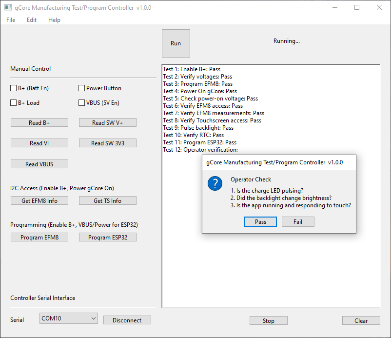
- Charge LED pulses when charging, turns solid when USB power is connected but charge is complete or blinks if there has been a charge error (for example timeout during charging).
- SD Card insertion detection. Status bit for ESP32 indicating presence of Micro-SD Card.
4-bit Micro-SD Card
All four bits of the Micro-SD Card connector are connected to the ESP32 allowing high performance 4-bit SD-mode access. I've seen up to a 5.5X performance increase for large writes over the typical SPI-based SD Card interface. The GPIO signals are also available on SMT pads if the SD Card is not being used.
USB Interface
A Silicon Labs CP2102N USB UART is connected to the ESP32 serial port and includes the traditional auto-programming (DTR/RTS) circuitry to put the ESP32 into boot mode.
Expansion Port
Unused ESP32 GPIO plus the GPIO used for the I2C interface are brought out to a connector along with both switched and un-switched 3.3V regulated outputs, a switched version of the battery rail, and other signals such as USB power and the power button signals for external circuits. The I2C interface is also available on a Qwiic compatible connector for easy connection to peripheral devices from Sparkfun, Adafruit and others.
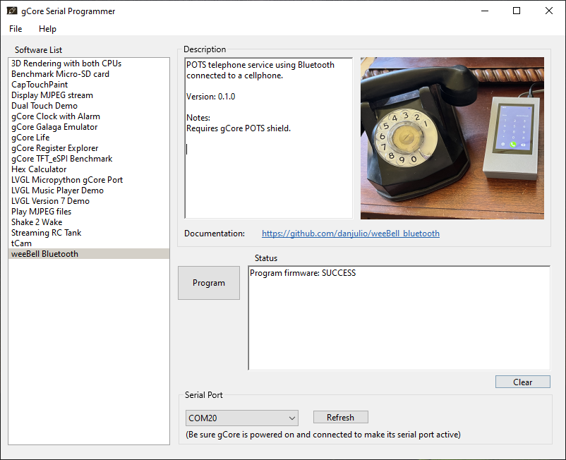
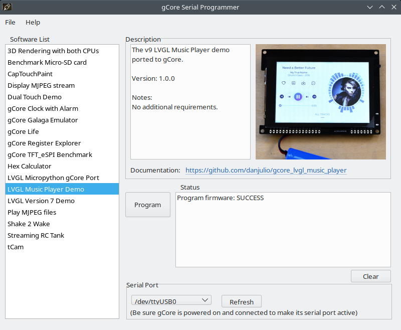
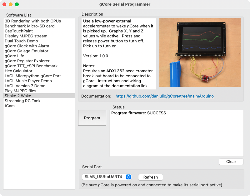
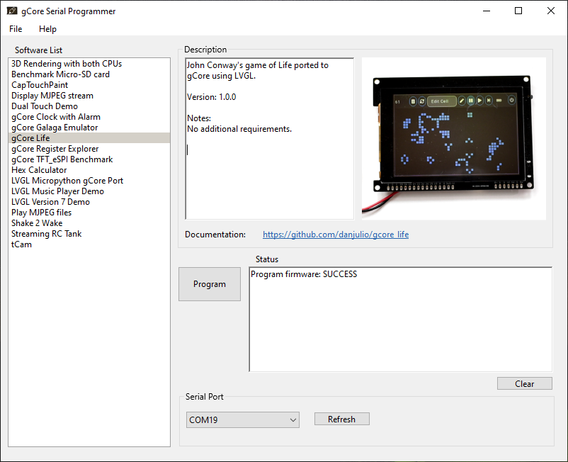
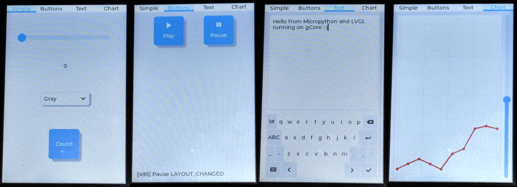
Software Support...
Read more »
 Andy
Andy
 radiona.org
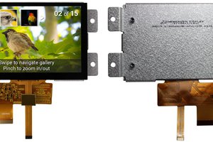
 Tim Wilkinson