Sagar 001
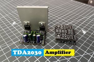
In previous tutorial I made a TDA2030 stereo based 28w amplifier. which is operated by external power supply. but how to use an amplifier without improper signal strength and frequency. That’s why preamplifiers come into market. Because I did not want more regulators/ wires and power supplies here in this circuit, I am making a preamplifier which runs without any power supply. here one thing may come in your mind, how we can change the signal specifications without powering the circuit. And that is possible due to band pass RC filters.

This will not amplify the gain but modifies the signal according to the requirement of BASS, treble or volume. TDA2030 comes with a closed loop gain resistor formula which then can be upgraded to get the possible amount of output.

This project is brought to you by JLCPCB, deals in PCB products like SMT assembly, stencil and PCBA. You can also check the partner companies which set an easy-to-use interface and better user experience for the JLCPCB. SMT assembly is starting in just $8. Sign-up now to get $54 new user coupon and get your PCB prototypes just in $2 for 5pcs two-layer board.
Working in Brief:
Let me show you how a band pass filter works, it consists of two filter one to block the higher frequency and other for the lower. Low frequencies are known as bass and higher are treble in audio engineering. Now just by tuning these two factors we can set a specific band of frequencies to pass. Which then amplify and produce the same output. Tuning can be done by making one of the RC component variables. In this case we are using potentiometers to set the frequency.
Low pass filter:
Audio signal is a mixed frequency signal which has low and high frequency components. The circuit can be made by using RC filter, capacitor possess a high impedance at low frequency. Means high frequency can be passed easily but its blokes the dc and has huge impedance for low frequency.

That’s why the circuit is grounded after a resistor with capacitor. So that high frequency signal is passed through the resistor and eliminated. Now we only have low frequency which simply known as bass. The band depend on the value of capacitor and resistor simply from the capacitor impedance formula.
High pass filter:
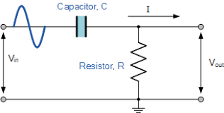
Same approach is used for treble/ high pass circuit. Here the capacitor is in series with the circuit and resistor is grounded. This time high frequency is passed through it, but low frequency component is blocked and grounded.
Components required:
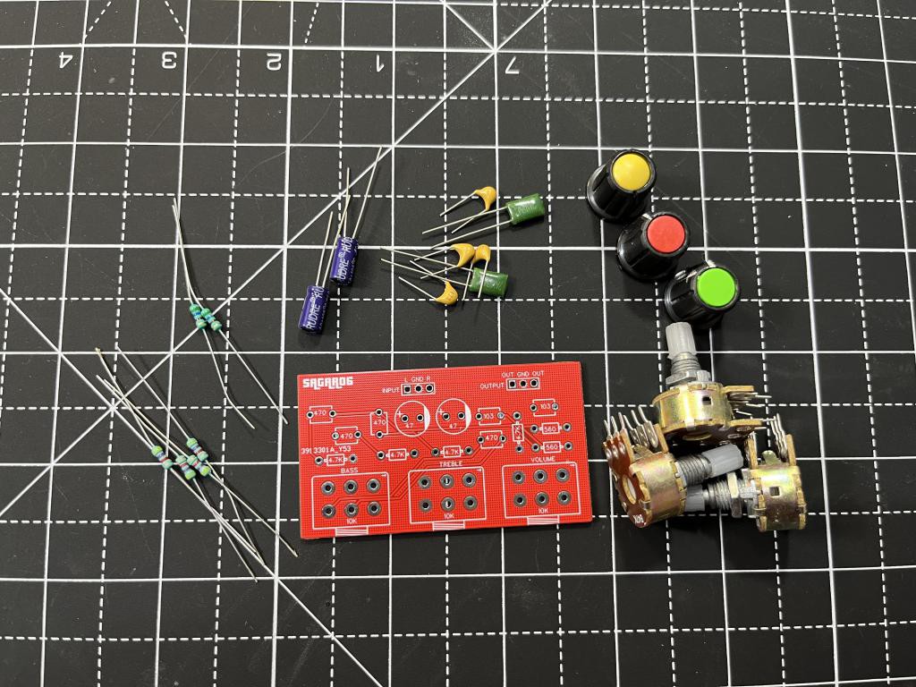
1) 47k potentiometers
2) 4.7k and 560R resistors
3) 47uf capacitors
4) 471 and 103 ceramic film capacitors
5) Custom PCB from JLCPCB
Circuit diagram:
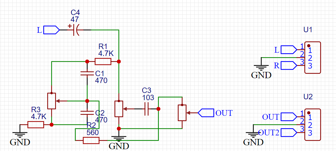
I made the circuit according to the above discussed theory. The signal goes first to the bass and treble circuitry and then to the volume control knob. The circuit behavior is determined by the low pass and high pass filters.
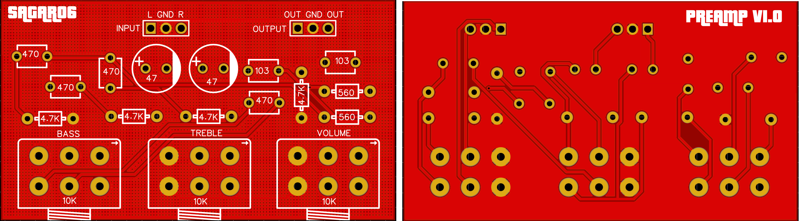
PCB design and layouts:
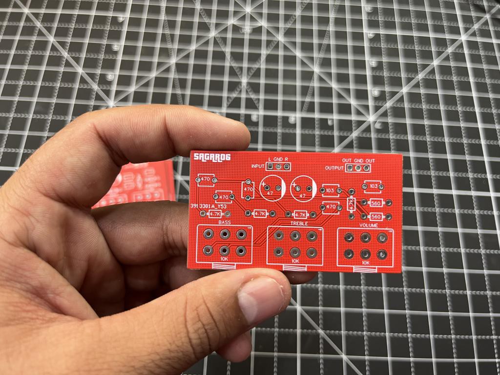
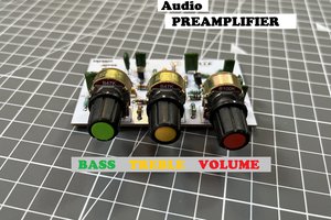
I designed the simple layout and place the Bass, treble and volume potentiometer in front of the PCB. You can mount this PCB in any home theater system also. This preamplifier circuit is the best bandpass without power supply. Download the Gerber files from here to repeat the project.
I am using JLCPCB prototyping service for the PCB and I got these amazing looking boards in just $2. You can see the quality and compare them with other manufacturers. JLCPCB is the only reliable and one stop solution to all your circuit requirements. SMT assembly service offered by them is very stable and easy to use follow this article to learn more about SMT services.

Components placement and soldering:
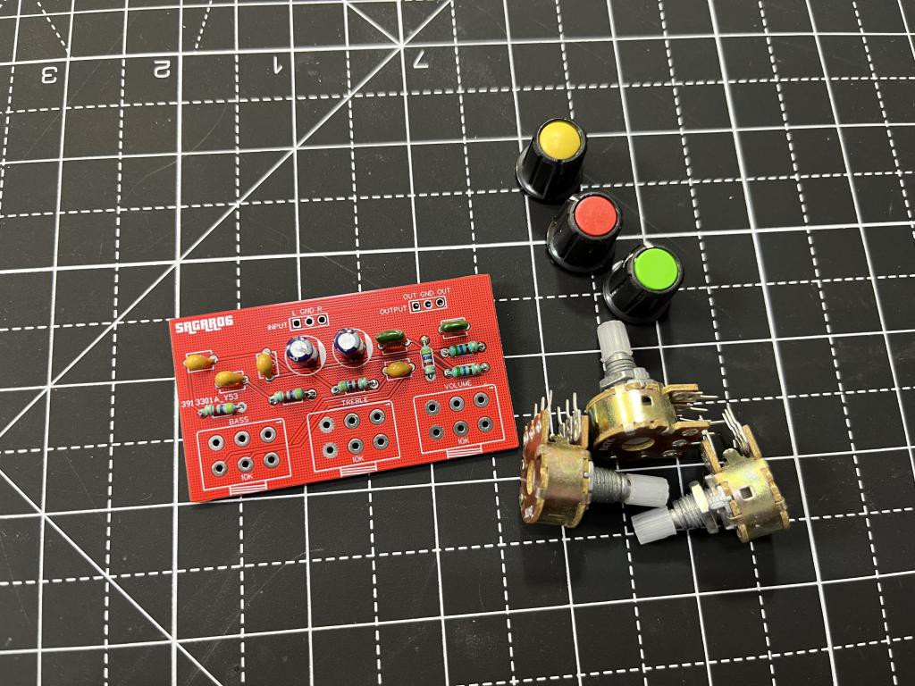
All the tracks are already done through the PCB now we just have to solder the components. I always go first with resistors and diodes. Because they are hard to mount if big components like capacitors are placed first. Then I soldered all the potentiometer and headers on the place. PCB is well labeled so that you can repeat the same project just by downloading these Gerber...
Read more »
 Lithium ION