NuclearPhoenix
Here are some of the most important key facts:
- Compact design: Total size 100 x 25 mm. 51 x 25 mm area for electronics and additional 49 x 25 mm to mount a small scintillator.
- Input voltage: 3.2 V - 5.5 V.
- Low-voltage device: No HV needed like with a photomultiplier tube.
- SiPM voltage range from 27.5 V to 33.8 V.
- Low power consumption: <5 mA @ 5 V in standard operation.
- Adjustable gain for the SiPM pulses, also affects pulse decay time and therefore dead time.
- TTL output for counting pulses or time-over-threshold applications.
- Additional raw pulse output if you want to manipulate the signal or use it for spectroscopy.
- Dead time only limited by the speed of the scintillator and the gain. Typically <10 µs.
- Only needs an additional cheap microcontroller to, for example, build a simple scintillation counter.
More information can also be found in the GitHub repository...
Ok nice, but how do I get it?
- DIY version: Download BOM and Gerber files or use Kitspace.
The principle of operation for the detector looks like this:

The PCB has four layers with components only at the top side. It mostly uses 0603 components or comparable IC packages to make it possible to solder it by hand and at the same time keep it as small as reasonable. This combination makes for the best signal properties while still being fairly affordable with today's PCB manufacturing prices.
This is what the PCB front side looks like: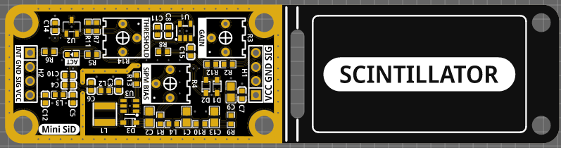
Connection between the Mini SiD and SiPM is done via some short cables soldered directly to the header on the right side. You can then lay the whole SiPM/scintillator assembly onto the PCB and secure it with cable ties. If you don't need the extra space you can cut off the PCB at the white line.
Depending on the scintillator size (which changes the amount of photons emitted), desired energy range and resolution, you'll probably need to change the gain and maybe also the discriminator threshold voltage. This will ideally only be done once, since you probably don't switch scintillators on a daily basis. If you just want to count pulses, gain is pretty much irrelevant for you.
I'm using an 18 x 30 mm scintillator and leaving the gain at the middle position to count pulses is more than enough.
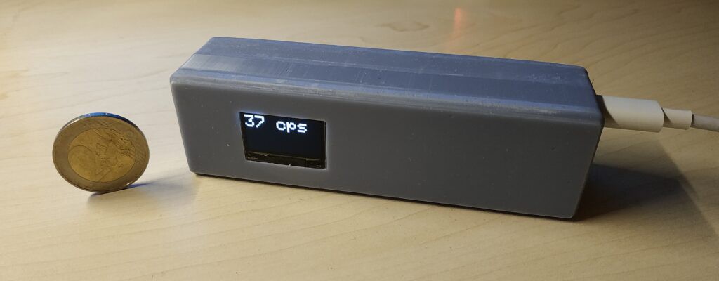
Scintillation Counter
A great project utilizing the Mini SiD is building a scintillation counter, which can be much more powerful than a geiger counter while being safer to use, because of the relatively low voltages.
One great example build has been done by RD-Gamma, who built one such device using a russian scintillator and a Broadcom AFBR SiPM.