 Peter Walsh
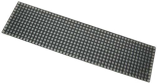
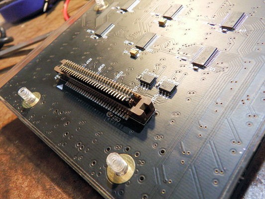
American Science Surplus is selling surplus SACO LED matrix boards for about $20 each. The boards measure 17-1/2" x 4-3/8", showing 12 x 48 (=576) LEDS.
Available here: https://www.sciplus.com/saco-led-matrix-board-62479-p
Interfacing a surplus SACO LED display
Already have an account? Log in.
To make the experience fit your profile, pick a username and tell us what interests you.
American Science Surplus is selling surplus SACO LED matrix boards for about $20 each. The boards measure 17-1/2" x 4-3/8", showing 12 x 48 (=576) LEDS.
Available here: https://www.sciplus.com/saco-led-matrix-board-62479-p
ConnectorClip.tar.gzDesign files for the lasercut connector clip.gzip - 6.77 kB - 11/12/2022 at 02:35 |
|
My first attempt at making a spot welder pen has failed.
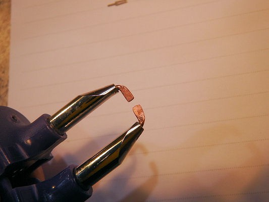
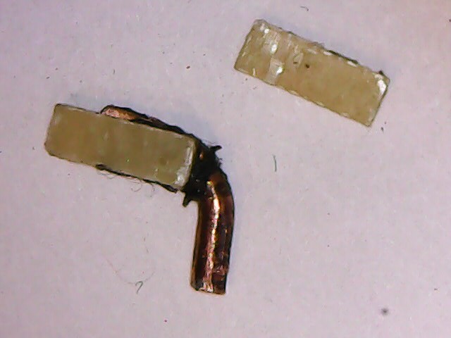
I bent the electrode ends of my existing spot welder pen inwards, then smashed them flat with a hammer and flat-end punch until they were about the thickness of the connector leads (about 0.02") as shown:
For side shields, I cut 2 nibbles from 0.03" PCB material and removed the copper plating, to make the shields even thinner.
Next, I glued the shields to one of the flattened electrodes using some JB weld:
The intent was to form a channel surrounding one of the electrodes that would corral the wire and connector lead and keep them from sliding off of the electrode, then the other electrode would slide into the top of the channel, pinning the wire and connector lead between the two electrodes.
This doesn't work.
Smashing the ends of the electrodes was the wrong process. The flattened ends are not accurately the right thickness, and the sides are not parallel so that the side shields angle in towards each other.
It seems like the corral idea should work if the electrode surfaces are the right thickness and parallel.
The bigger issue was in the pen itself. The cheap Chinese spot welder pen was not made for pinching things together, the end hinge failed (for that purpose), and holding the sides of the pen together is too clumsy.
The solution might be to build a bespoke pen with a captured hinge.
At this point in the project I *could* design and order a PCB for debugging and development, but not yet.
I'd rather start with some bodge wiring and see where that leads. The wiring map (developed by Connor Huffine) might have some bugs, the LED panel might turn out to be damaged (or complete crap) and I really want to see if I can weld the bodge wires.
Bodge soldering 0.05" header pins is tricky and a PITA, so I've been meaning to try welding instead.
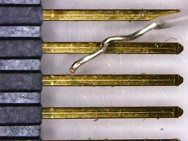
With a great deal of fiddling, I managed to get a wire and the header pin between the two electrodes of my battery tab welder and tried welding.
Surprisingly, this appears to work very well. The wire ended up weld-bonded to the header pin, and pulling the wire with reasonable force (force close to the yield strength of the wire) does not make the weld come loose.
The official test of a spot weld is when you pull two pieces apart: if the spot weld is any good, the material will fail before the spot weld and you'll end up pulling out a section of the material instead of breaking the weld.
...and that's exactly what happened!
A sufficiently convenient jig that holds the wire against the header pin between two electrodes should work, then I can apply a line of hot-glue to the welded wires/pins to act as strain relief.
Using a header as a substitute connector is good, but not mechanically sound.
The header leads are bent at an angle, and the header tends to push up out of the connector well and be loose. It would be useful to have a "clip" of sorts that holds the header against the connector pins.
Fortunately, the connector itself is made to accept a clip-type mating connector.
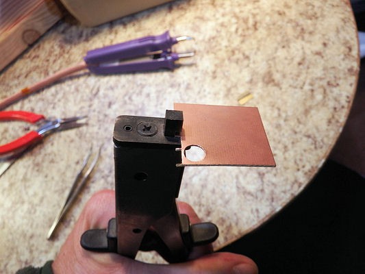
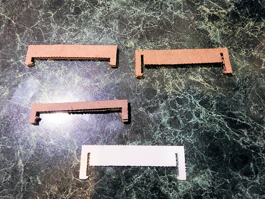
Some initial attempts were made in cardboard to home in on the final design, then an actual clip was cut from thin polystyrene (white, in image below) using a laser cutter.
There's nothing special about polystyrene, it's just what I had on hand. Anything that's thin (thinner than the clip landing on the connector) should do. The landing is roughly 1mm wide, so any laser-cuttable scrap of plastic should work.
I'm guessing that a clip could be 3d-printed, probably the features are too small for FDM but SLS could do it.
The clip works well. It snaps into place, doesn't come out, and gently presses the header pins onto the connector pins.
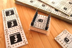
I have a selection of PCB header strips, in 0.10" and 0.05" and single and dual rows.
The 0.05" header pins align with the connector pins, so a header might form the basis of a suitable connector. Two single-row headers glued together have pins that are too wide, but a double row is too narrow.
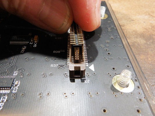
Start with the double row header.
Now the pins are too narrowly placed to mate with the connector pins, but if we bend the pins out just slightly it might work.
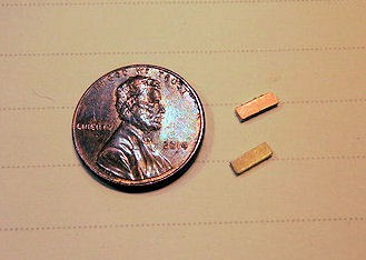
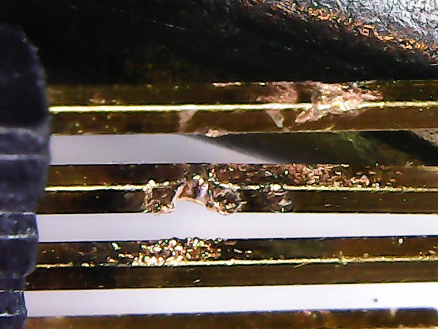
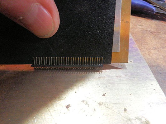
After some experimentation, I found that a thin piece of brass and a thin piece of plastic would fit between both rows of headers. Then a thicker piece can be pressed between these two, and the header pins gently bent outward.
Shown below is the brass (yellow), thin plastic (black) and a thicker piece of aluminum pressed between them. The aluminum piece is too thick to go between the pins, so pressing down on it causes the pins to splay outward.
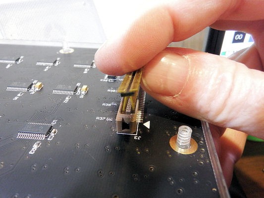
And... that works. With the leads slightly splayed, the header fits into the connector slot and the pins make contact with the header pins.
Testing a few of the pins WRT the header shows good contact everywhere.
User Connor Huffine started a project using these boards, and I *think* I remember a HAD article touting his project a few years back.
He did a lot of the heavy lifting for this project - figuring out the connector pinouts, tracing the power supply circuitry, and so on.
Then... nothing.
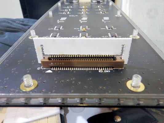
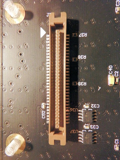
The reason no one's been able to interface with the boards is that they have non-standard connectors. The data connector (shown below) *appears* to be a SCSI-type connector, but with 60-pins. These aren't available anywhere that I could find.
So the first step is to see if I can hack together a data-interface connector.
If I can't manage this first step, then I'm just going to toss the boards in the trash.
 deʃhipu
 Alex
Alex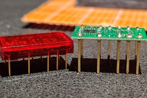
 Jacob Still
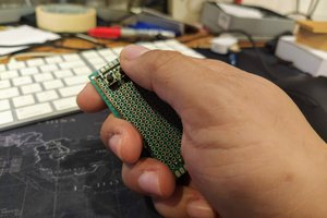
 parasquid
The main connector seems to be a 3M "Pak 50" part number P50L-060S-AS-DA. Yeah they are impossible to get for anything approaching reasonable prices. I appreciate the effort you've made into cobbling your own connector but honestly I've just removed it entirely and will be replacing it with a much easier to get 1.27mm pitch pin header.
Also Connor's pinout is correct except the pedant in me swapped Bank 1 and Bank 3 so that LED1 (They're numbered on the PCB) is in Bank 1. Because of the interlaced way the data gets loaded into the drivers, the display will be garbled if software written assuming one convention is used on a panel mounted the other way... data connector is on your left when looking at it from the front!