 charliex
Saturday we started measuring the XY backlash after last weeks tear drop circle, and wow 0.05" and .003" ! the Chinese Factory says 0.008 to 0.003" which ain't great but its a ways away from where we are.
The Y setup on the G0704 is not great, its held only at the front and the back is left to whip around.
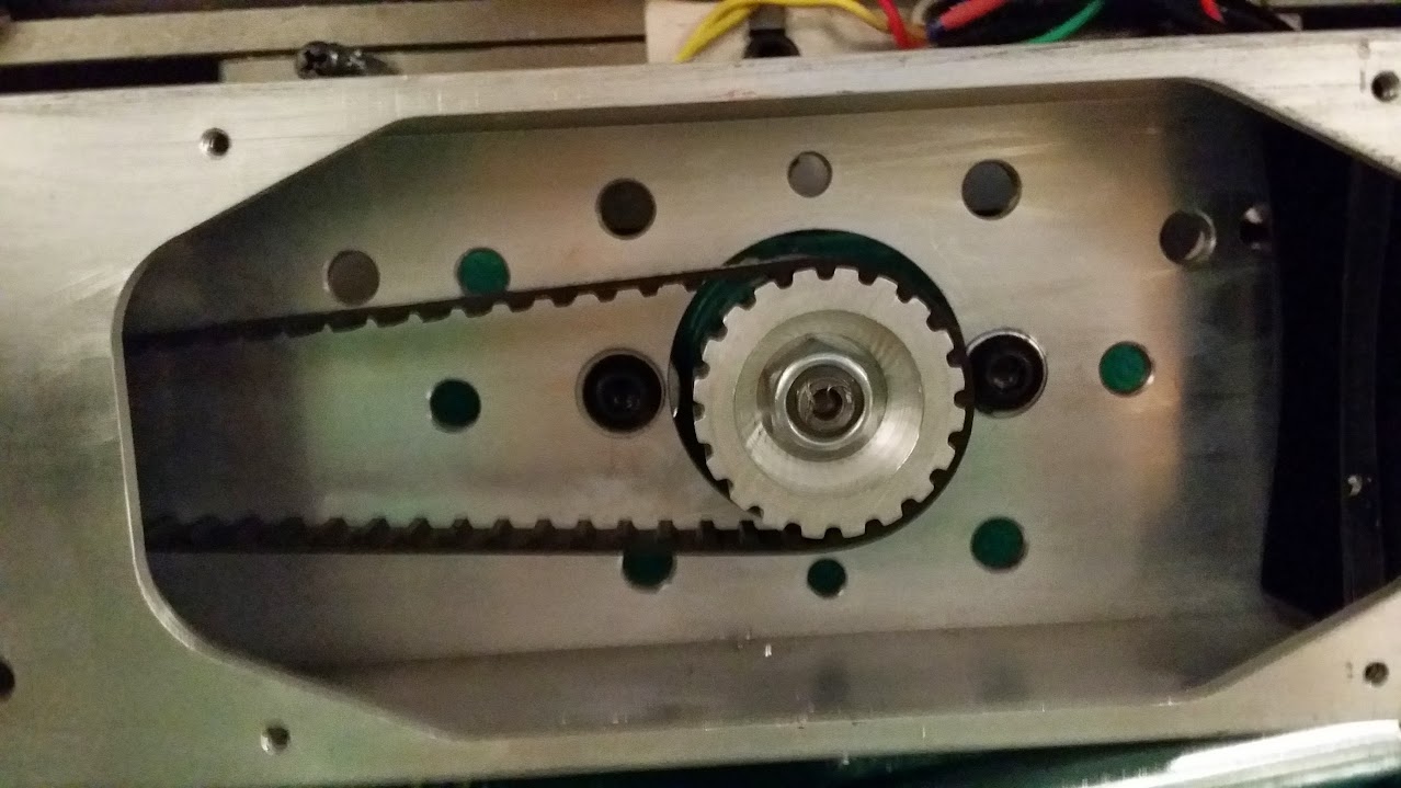
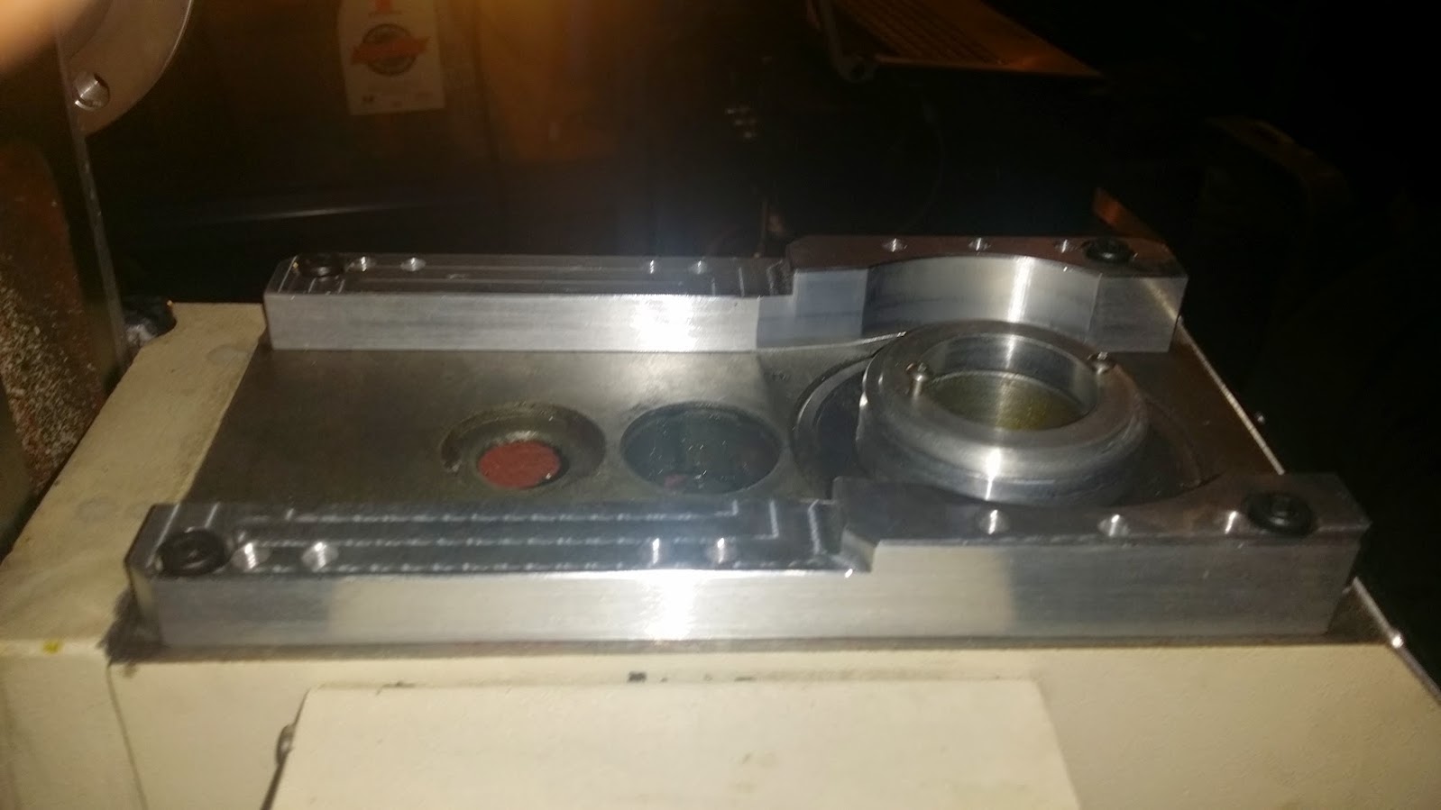
this is what the Y side with the flash-cut conversion (sans pulley)

We couldn't get the slop out with the pulley and its two little allen set screws, so i figure cut holes out the middle and put a couple of nuts on (M8 1.25 )
mmca bust out the HF lathe (which is a whole other thing)

after modifying the pulley
that reduced our backlash to about .009" on the Y still terrible, but can't see a way to make it better. the Y motor mount relies on holding the motor box etc with a couple of normal bearings. So at this stage, its OK and we'll just change the lead screws to double nut ball screws.
next the belt drive, unfortunately often as we do these projects , something cool happens and we're all like hey that'd make a great video and we need photos. but as usual we only recall that after its done....

top cover off.
wiring box exposed to cut one black motor wire. and remove the white from the speed controller dial, bottom white.
the other wire off the side is the "safety" interlock for the plastic guard.

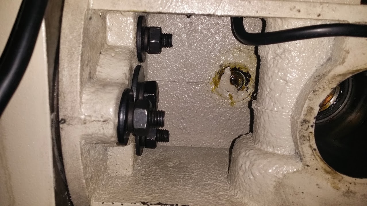
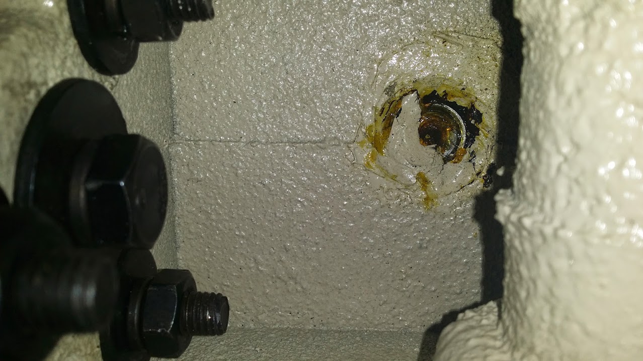
motors off, its just 4 bolts, remove the wires.
you don't want to whale on this so we used the HF pulley puller which i happened to have around since i use it for supercharger pulleys etc. No pics of this stage..
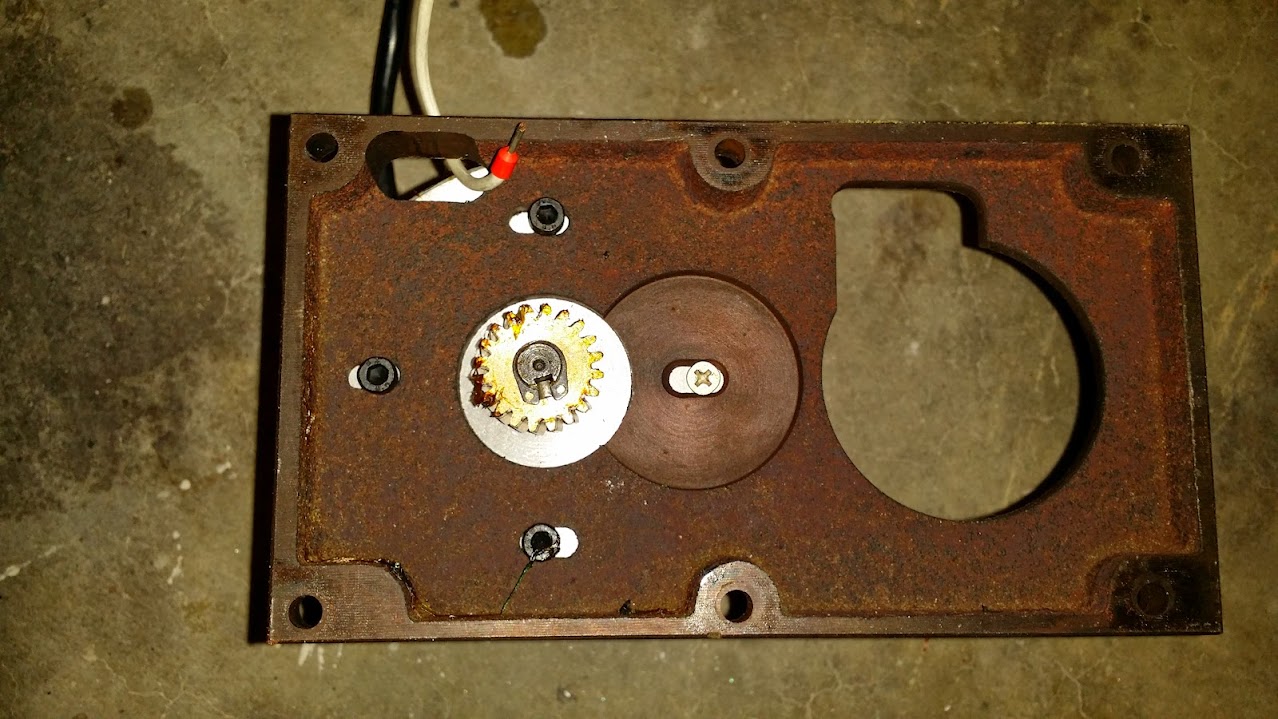
Which gives us this.

the draw bar mech needs to be removed. encoder wheel, sensor etc..

two bolts to remove the metal barrier, same for encoder. of course i did get pics of the easy stuff.


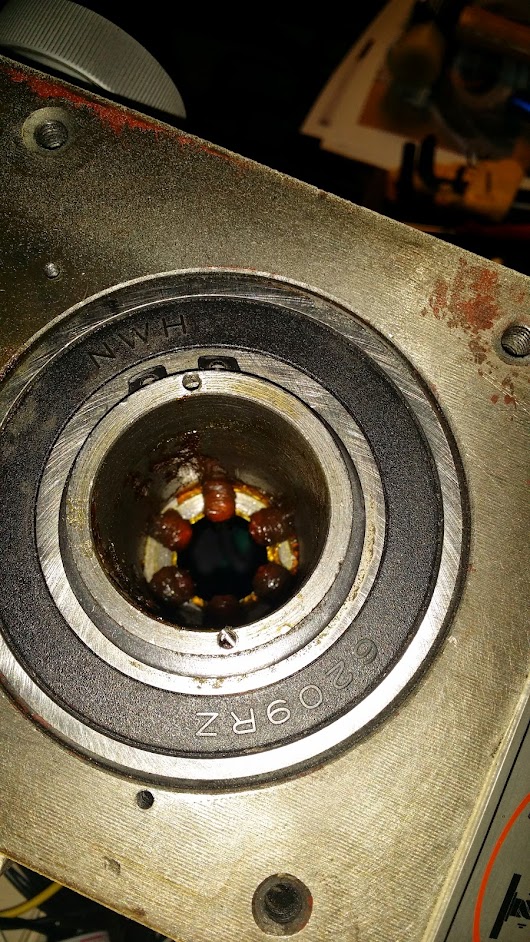
and then like 90% of the instructional things on the internet , suddenly
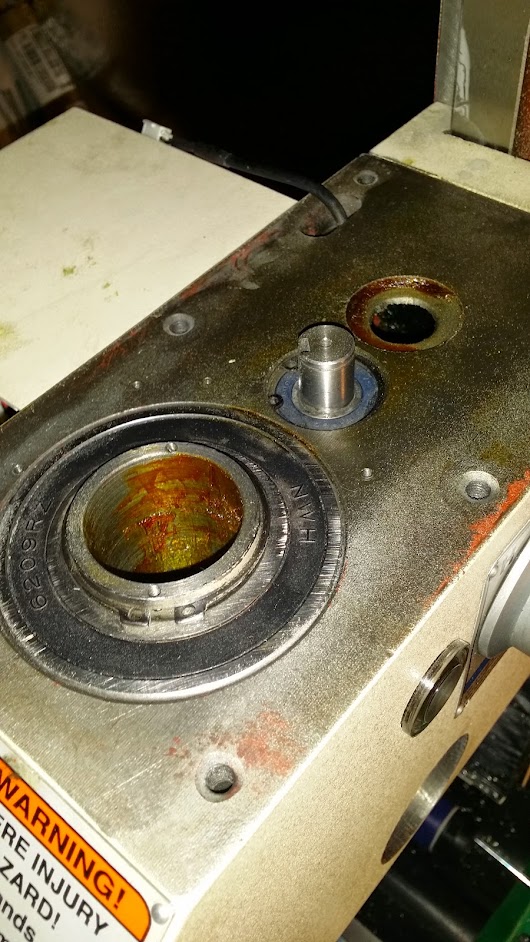
 spindles out, you press down the spring loaded part, i used a flat blade screwdriver then pop off the C retaining clip its not sprung its just like a thick cut washer, rotating it around a bit and you'll find the sweet spot where it'll just pop off , then easy back on the spring and lift out the round tube and spring.
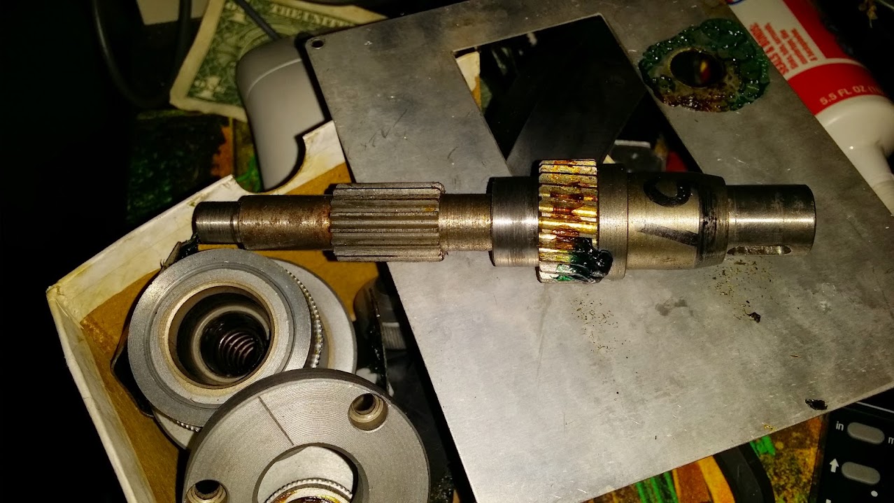
here's one i made earlier

at this point, replace the bearings... and remove that C spring.
for sake of argument, lets say we did that.
pull the front off, four bolts for the plate, two screws the super duper DRO..

ZERO here means that is the name of the button. in and mm mean something other than measurements.
the up and down arrow randomly change the inaccuracy.
arko had jumped ahead and pulled the quill side off, so we pulled that gear
from here. it's easy to remove, a set screw on the quill handle , pop it off and pull the above gear out.

now the front adjustment, not sure what mmca is pointing at.
 same again, set screw lift out the dial, and then the gear/shaft comes out but!
 this threaded rod needs to come out, luckily its the same sized thread as a bunch of other, so i just threaded a bolt in and pulled it out. that allows you to pull that front Z quill out.
top gear off, c clip and lift off with a flat blade, its plastic and we don't care about it. at first you're like, c clips, i hate them so much wheres that special tool i bought one time, turns out these are really soft and you can just use the key-way slot to pop them off with a small screwdriver and a pair of pliers. they're not being used again.
loosen the head rotation bolts. all four
rotate head thus.

we're going to tap this out with a piece of precision expensive drill rod that we're using to calibrate the spindle later..
remove this cover at the back of the head

remove the set screw at the bottom.
 you can then lift out the fork between the gears, it just fell off for us when the screw was out.
then you can remove the H L dial watching out for the ball bearings and detent plate, its a set screw again.
now any c clips are removed from the top of the shaft., tap the bottom side ( normal underside of the shaft when head is at 0o rotation) with the most expensive precision piece of rod you have close to your fingers, the gears will slide off with the help of the blue and green grease that is everywhere. and you can then just rotate the shaft and gears towards you and take the whole thing out through the rear cut out. .
rotate the head back and snug the bolts.
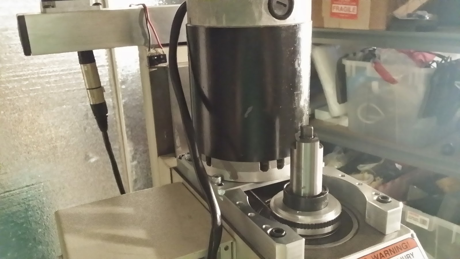
it should start to look like this

clear off the top
 install side mounts for motor and tap on the pulley to the spindle, fire is recommend but we gently hammered it on there with a protective piece of metal over the pulley. taking care to align the screw holes.
our screw holes were off in the kit

after test fitting the motor which as had the old gear removed with a set screw and pulley puller. then gently put the new belt pulley on there, it didn't clear the hole..... so i started to hand file it because grinding dust is exactly the kind of dust you do not want on the ways of a mill... but after about 5 minutes with a file that was too big i'd only made about 1 mm in. so time for the dremel. I covered up the machine with a drop cloth everywhere. then proceeded to grind it off.


 notice my use of the special blue shop towels that are inflammable.
 after the battery ran out on the dremel i decided that was the right amount to remove.
and tada! , dremel engineers had exactly calculated that a fully charged battery grinding away at a g0704 would run out at precisely the right point. Thank you DE. Clean EVERYTHING after grinding, remove the drop cover really carefully.
motor mounted with 60 lbs of force applied to it, to tension the belt.
now add wires back, and plug it in and it'll all work perfectly, except the sharp eyes will notice the lack of an encoder ring. more on that later.
I drilled a hole in the top of the control box to run the encoder + connector and motor wires into, this needs a grommet to stop the vibration of the machine slicing into the wire and stopping debris getting in the box where the magic smoke livs.milling
waiting for the youtubes to process that last 3 videos into one.
so its almost circular, but a lot better than it was.. .time to ditch the flashcut hardware mounts and leadscrews and install ballscrews. the feed and speed needed to be set, but it was like 2AM and no RPM and i realised the timing light i was going to use was for ignition advance, so i could tell you exactly how many degrees of retard/advance the motor was running at.
Discussions
Become a Hackaday.io Member
Create an account to leave a comment. Already have an account? Log In.