 Bulbul
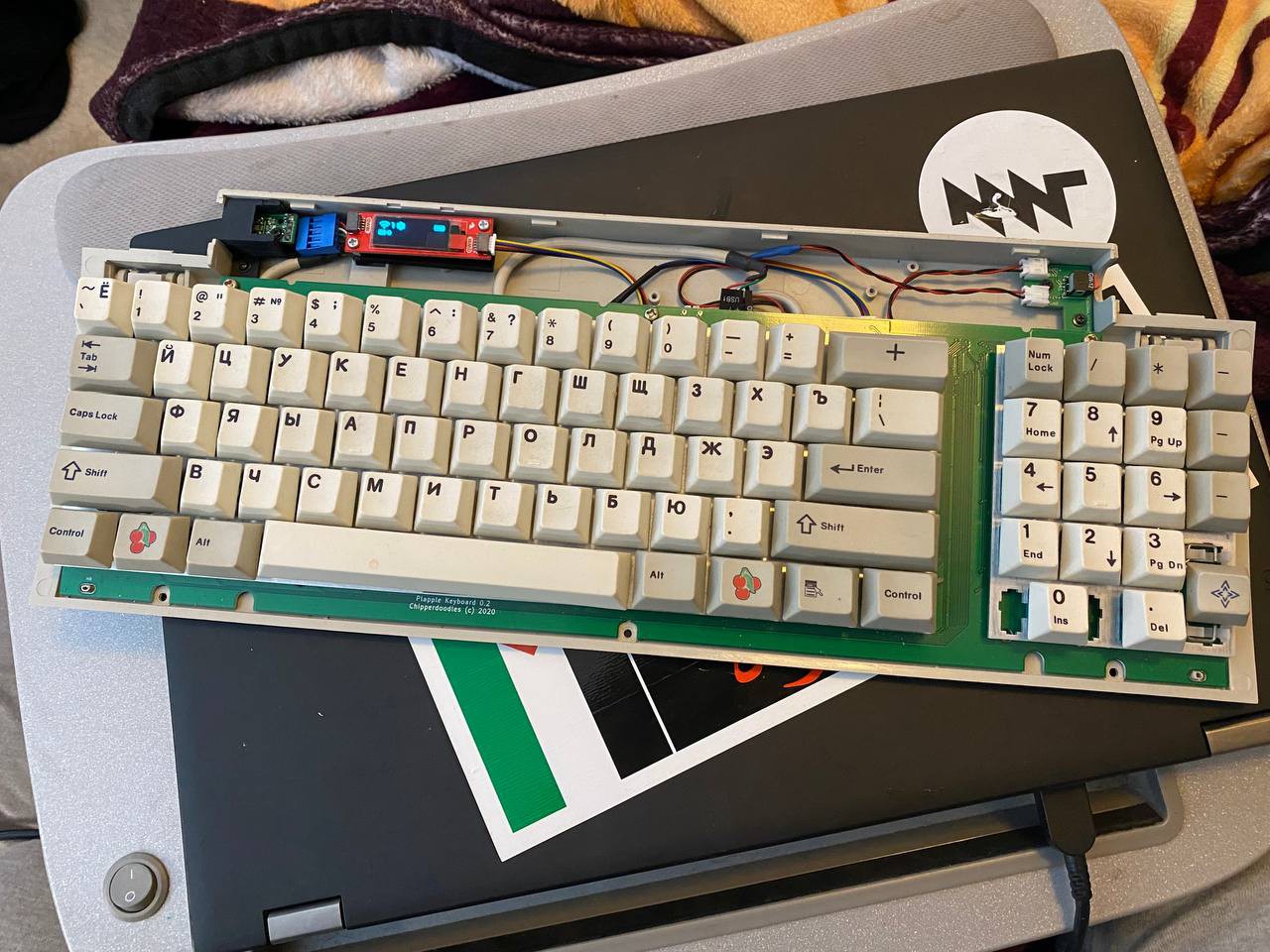
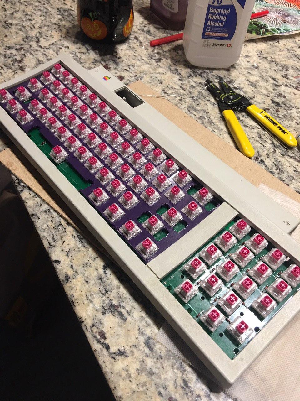
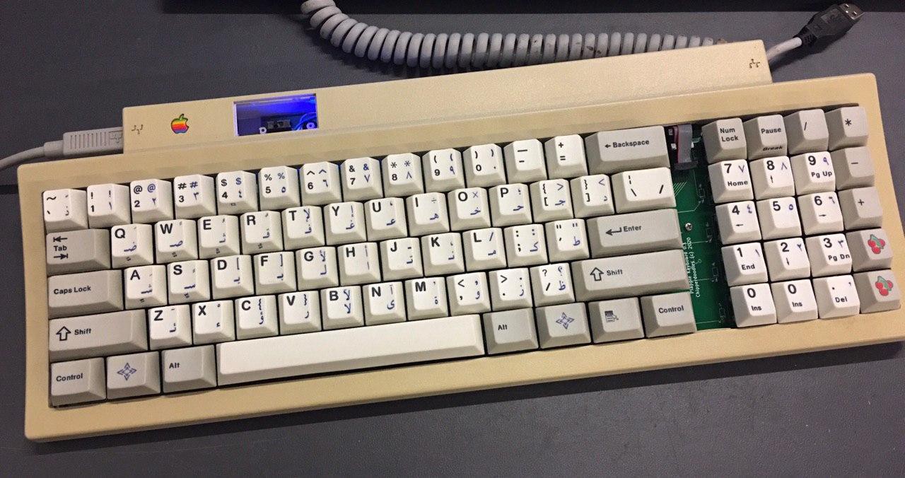
The apple keyboard II was the cheaper option for late 80s early 90s option macintosh computers, It used some interesting switches with rubber dome and a membrane sheet. I had an old one sitting around that had some broken keys (the rubber had broken) and with some keyboards under my belt I decided to take a stab at seeing if i could replace the internals with a proper pcb based, modern mech switch board.
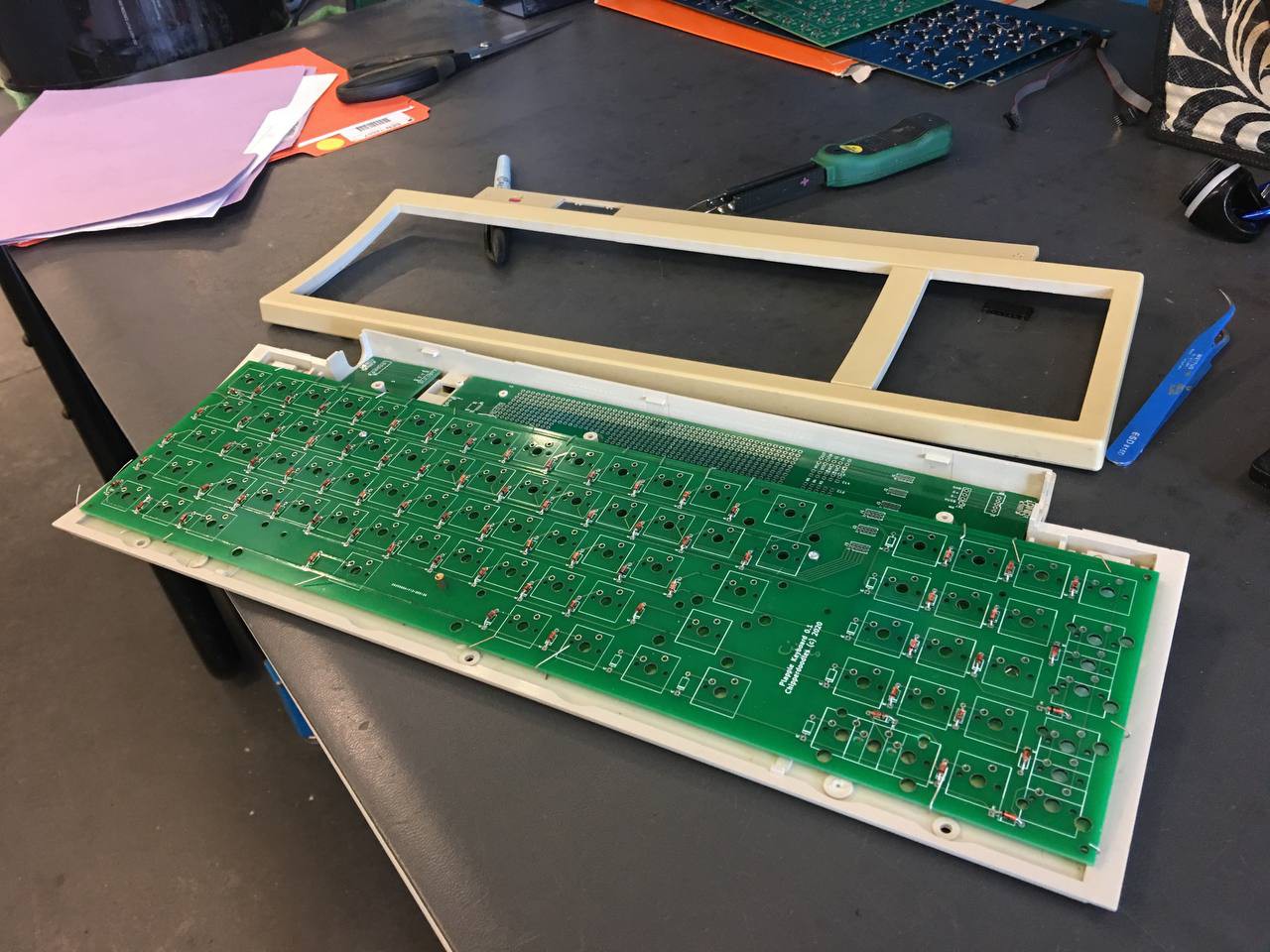
This has been an ongoing project for a while with several iterations. The current version just needs minor tweaks I consider mostly complete. there is room for 2 pcbs, the keyboard and peripheral board. the peripheral board is unnecessary and leaves room for some modular design ideas.
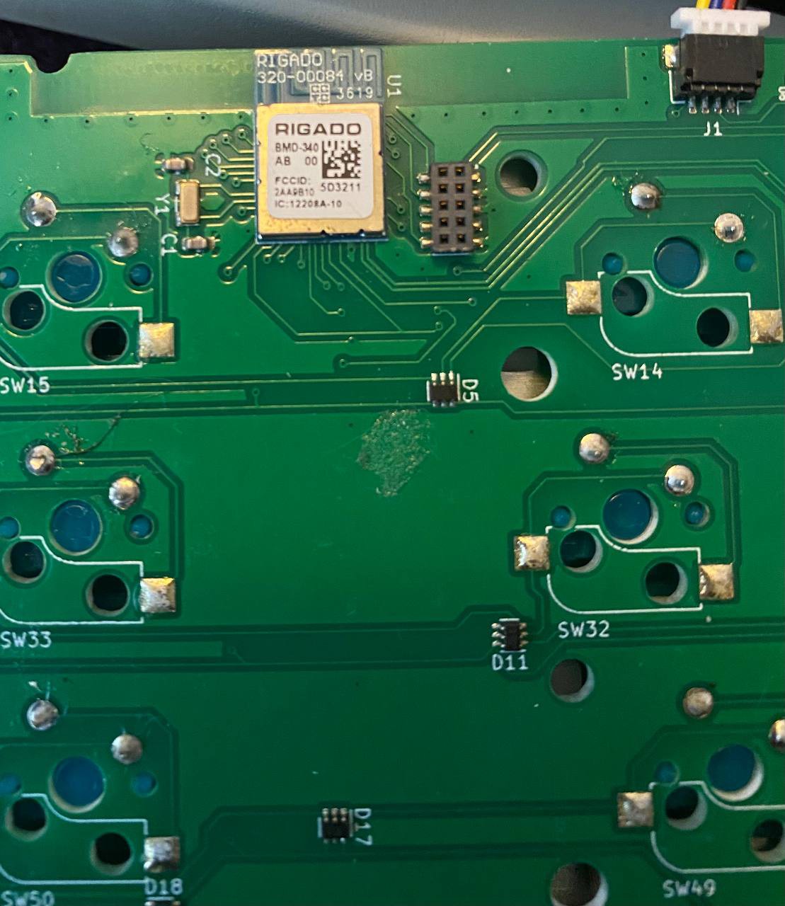
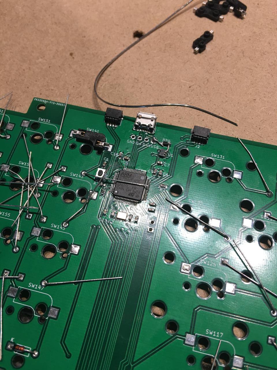
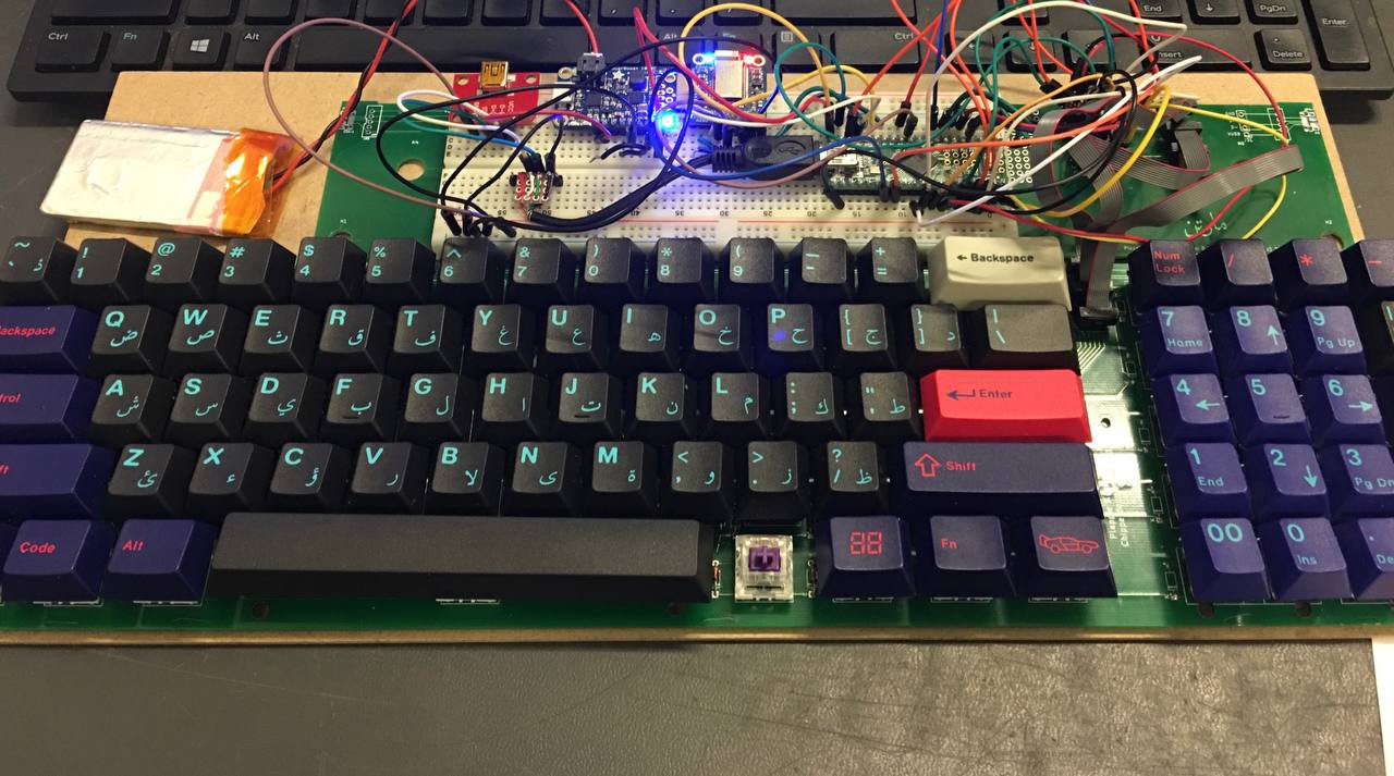
Currently I have a successful Nrf52840 based Bluetooth keyboard that runs ZMK. The fit is decent and functional. With much of the work done in the past I'll use project logs to try to recount the progress. I will open source the board eventually once I've cleaned them up.
Project bits:
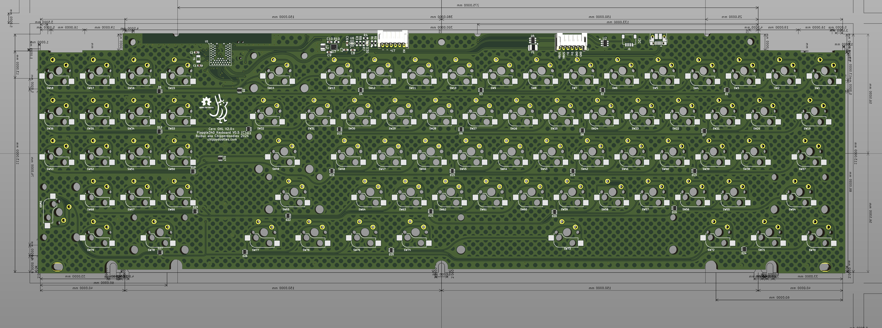
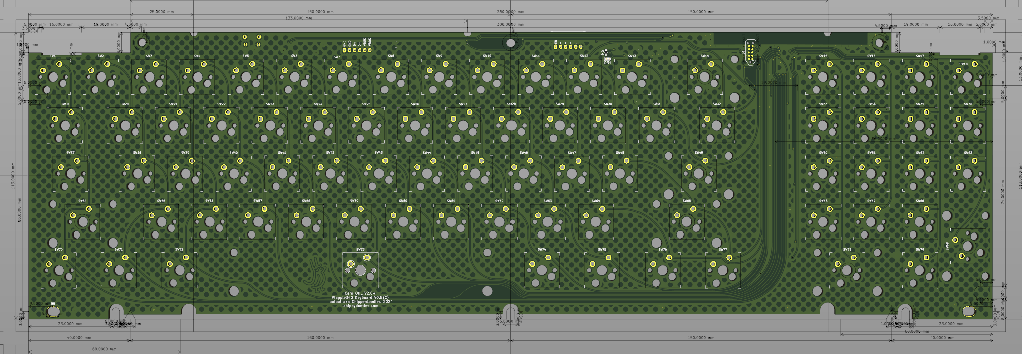
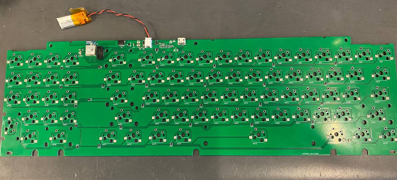
* Keyboard PCB
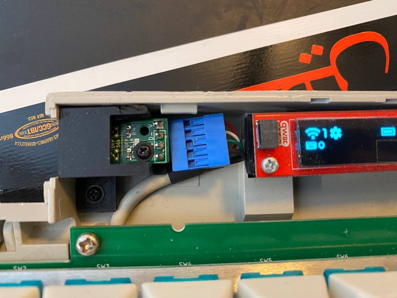
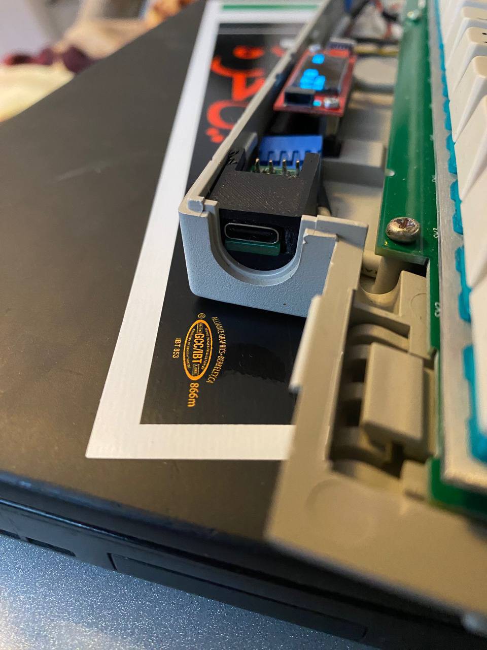
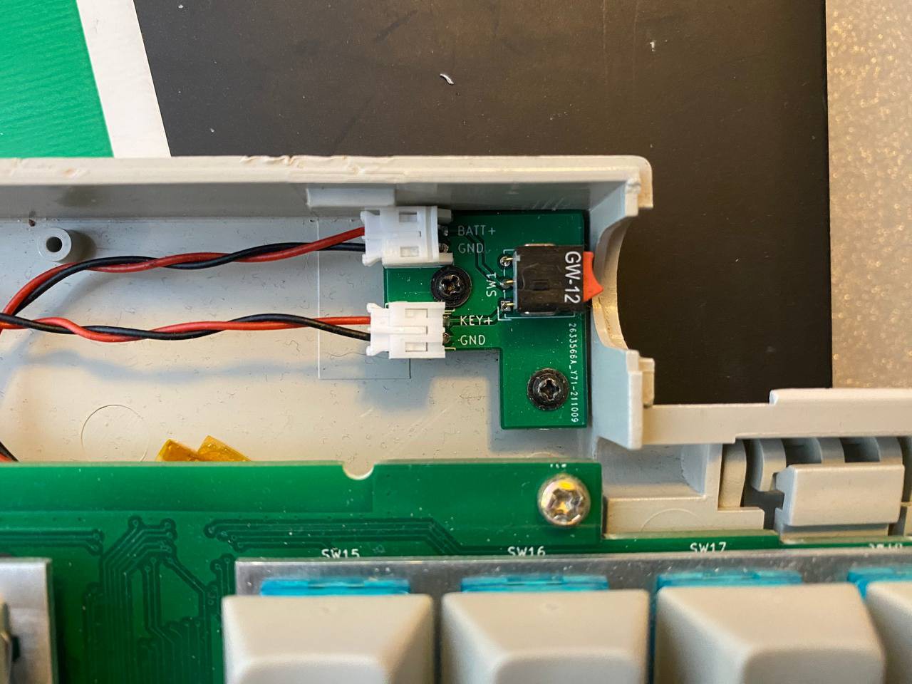
* Daughtercard adaptors for usb C and power switch
* Firmware with ZMK


 RasmusB
 Ironpark
 Mx. Jack Nelson
 Nguyen Vincent
any news on this? I’ve also got a broken apple keyboard ii and would love to do this conversion. From my quick google searching, it looks like you’re the only one doing this, so I’d love to get a hold of the pcb.