The circuit of this project is very simple which contains Arduino, keypad module, buzzer, Servo Motor, and LCD. Arduino controls the complete processes like taking a password from the keypad module, comparing passwords, driving buzzer, rotating servo motor, and sending status to the LCD display. The keypad is used for taking the password. The buzzer is used for indications. Servo motor is used for opening the gate while rotating and LCD is used for displaying status or messages on it.
First of all, we start from the brain of this project which is the Arduino UNO board. The Arduino board is connected to an LCD and a servo motor. The servo motor is used to push (lock) or pull (unlock) the latch on the door. A 16 x 2 LCD is required to display the message by Arduino, 16 x 2 means it has 16 number of columns and 2 number of rows.
The complete Arduino Door Lock Code can be found at the bottom of this page. You can directly upload the code, but it is recommended to read the below paragraphs to understand how the code works. Also, it is important to make sure you have added the following keypad library to your Arduino IDE to compile the code successfully. To do that just open the link below and download the ZIP file. Then on your Arduino IDE navigate to Sketch

After inserting all the header and library files, assign all the pin for LCD and define the password length and set the initial position of the servo to 0. After that, take a “char” datatype for declaring the number that can hold it including the null character.
//#include <Keypad.h>#include <LiquidCrystal.h>#include <Servo.h>Servo myservo;LiquidCrystal lcd(A0, A1, A2, A3, A4, A5);#define Password_Lenght 7 // Give enough room for six chars + NULL charint pos = 0; // variable to store the servo positionchar Data[Password_Lenght]; // 6 is the number of chars it can hold + the null char = 7char Master[Password_Lenght] = "123456";
With this piece of code (char Master[Password_Lenght] = "123456";) -- under the Char Master, I declare the password of the door lock, then assign the number of rows and columns in the keyboard and also declare keyMaps and connect with rows and columns. Under the void setup, initialize the servo signal pin D9, servo status closed and print the name of the project/device/company with 3 seconds of delay on LCD time of starting the device.
void setup(){ myservo.attach(9); ServoClose(); lcd.begin(16, 2); lcd.print(" Arduino Door"); lcd.setCursor(0, 1); lcd.print("--Look project--"); delay(3000); lcd.clear();}
Under the loop function, the simple if-else condition is there. According to status (it’s locked automatically), print “Door is close” with 3 seconds of delay and servo rotate to close position, door data count as 1 otherwise door locker remains open and data count 0, servo open rotate to the position goes 0 degrees to 180 degrees and to close it goes from 180 to 0. The servo open and servo close functions are shown below.
void ServoOpen(){ for (pos = 180; pos >= 0; pos -= 5) { // goes from 0 degrees to 180 degrees // in steps of 1 degree myservo.write(pos); // tell servo to go to position in variable 'pos' delay(15); // waits 15ms for the servo to reach the position }}void ServoClose(){ for (pos = 0; pos <= 180; pos += 5) { // goes from 180 degrees to 0 degrees myservo.write(pos); // tell servo to go to position in variable 'pos' delay(15); // waits 15ms for the servo to reach the position }}
Write the position of the servo with 15 seconds of delay to reach the servo position. Under the void open function, print on LCD “Enter Password” then the condition specifies that the entered password should be same with custom key, within this body data counted and stores char into the data array, incremented and input password printed on LCD if the data length (number of key) and input password matches with Data Master (where the pre-defined keys are present). Then as an action LCD clear, servo drive, print on LCD “Door is open” and the data counter is reset to 0.
If the input key does not match with Data Master, as an action on LCD clear print on LCD “Wrong Password “ to notify with 1 second of delay and remains in its lock position with data counter sets to 1 and continue this process in a loop.
if (data_count == Password_Lenght - 1) // if the array index is equal to the number of expected chars, compare data to master { if (!strcmp(Data, Master)) // equal to (strcmp(Data, Master) == 0) { lcd.clear(); ServoOpen(); lcd.print(" Door is Open"); door = 0; } else { lcd.clear(); lcd.print(" Wrong Password"); delay(1000); door = 1; } clearData(); }When users enter the “*” key it will allow the user to enter the password. Now, it checks the password stored in this Arduino EEPROM. If it is correct, it will show ‘Access is granted, welcome‘, and then the door is opened. But, if the password is incorrect then it will go back to the standby mode by displaying “Incorrect Code Get Away“.
Similarly, in Arduino Password Security Lock System, if the user press “#” it will ask for the code. Now, if the entered code is incorrect then it will get back to standby mode. and if it is correct it will ask the user to enter the new password and confirm the password by retyping it. Here, the Arduino will compare the code, if it is incorrect then again it will get back to standby mode. But, if it is correct then it will change your current password.
Here we have initialized the button. we have declared a variable code to store the default code. Again we have created two variables check1 and check2 to check the user entered code is right o wrong. short variable to use later. We have initialized keypad and servo.
LiquidCrystal_I2C lcd(0x27, 16, 2);Keypad myKeypad = Keypad(makeKeymap(keymap), rowPins, colPins, numRows, numCols);Servo myservo;void setup(){ lcd.init(); // initialize the lcd lcd.backlight(); lcd.begin (16, 2); lcd.setCursor(0, 0); lcd.print("*ENTER THE CODE*"); lcd.setCursor(1 , 1); lcd.print("TO _/_ (Door)!!"); //What's written on the LCD you can change pinMode(Button, INPUT); myservo.attach(11); myservo.write(0); // for(i=0 ; i<sizeof(code);i++){ //When you upload the code the first time keep it commented // EEPROM.get(i, code[i]); //Upload the code and change it to store it in the EEPROM // } //Then uncomment this for loop and reupload the code (It's done only once)
let’s discuss the setup part of the program. we have initialized the LCD. then we have printed information to the LCD. we have configured the button pin as the input pin. here, we use the button pin to close the door. this is the pin D11 of Arduino at which the servo is attached. Initially, we gave the servo to stay at angle zero.
myservo.write(0);
Use of ReadCode Function
Before discussing the loop function, let’s discuss the ReadCode function used in the keypad. we can only get single characters to type the word. so we have used a while loop. let’s discuss it in detail. This while loop does not stop until you press A. Basically, this while loop stores the password and display Asterisk * on its behalf. on the second loop, it checks the password typed is the same or not. It will increment on match and decrement on incorrect.
void ReadCode() { //Getting code sequence i = 0; //All variables set to 0 a = 0; j = 0; while (keypressed != 'A') { //The user press A to confirm the code otherwise he can keep typing keypressed = myKeypad.getKey(); if (keypressed != NO_KEY && keypressed != 'A' ) { //If the char typed isn't A and neither "nothing" lcd.setCursor(j, 1); //This to write "*" on the LCD whenever a key is pressed it's position is controlled by j lcd.print("*"); j++; if (keypressed == code[i] && i < sizeof(code)) { //if the char typed is correct a and i increments to verify the next caracter a++; i++; } else a--; //if the character typed is wrong a decrements and cannot equal the size of code [] } } keypressed = NO_KEY;}
Getting Code From Keypad
let’s discuss the getNewCode part: Here, we are initializing two characters i=0 and j=0. This code is just used to print command on LCD. we have already discussed the while loop part before only one thing is different that is the check part. it stores characters in the array.
void GetNewCode1() { i = 0; j = 0; lcd.clear(); lcd.print("Enter new code"); //tell the user to enter the new code and press A lcd.setCursor(0, 1); lcd.print("and press A"); delay(2000); lcd.clear(); lcd.setCursor(0, 1); lcd.print("and press A"); //Press A keep showing while the top row print *** while (keypressed != 'A') { //A to confirm and quits the loop keypressed = myKeypad.getKey(); if (keypressed != NO_KEY && keypressed != 'A' ) { lcd.setCursor(j, 0); lcd.print("*"); //On the new code you can show * as I did or change it to keypressed to show the keys check1[i] = keypressed; //Store caracters in the array i++; j++; } } keypressed = NO_KEY;}
In getNewCode2 we are repeating the same process. we are using the check2 variable to store the retyped password in the array.
void GetNewCode2() { //This is exactly like the GetNewCode1 function but this time the code is stored in another array i = 0; j = 0; lcd.clear(); lcd.print("Confirm code"); lcd.setCursor(0, 1); lcd.print("and press A"); delay(3000); lcd.clear(); lcd.setCursor(0, 1); lcd.print("and press A"); while (keypressed != 'A') { keypressed = myKeypad.getKey(); if (keypressed != NO_KEY && keypressed != 'A' ) { lcd.setCursor(j, 0); lcd.print("*"); check2[i] = keypressed; i++; j++; } } keypressed = NO_KEY;}2C LCD communicates with the Arduino through the I2C protocol. Different Arduino boards have different I2C pins. The I2C pins on Arduino Uno and Arduino Nano are A4, A5.
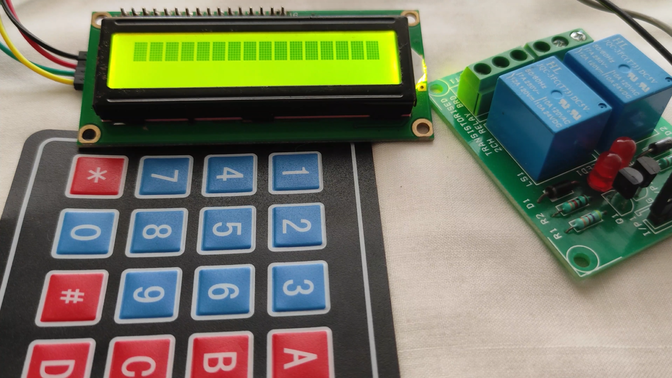
Next connect the keypad with Arduino. The 4X4 keypad has 8 connections but we don’t require the last column of keypad. We only require numbers for the password. So we won’t use the last pin of keypad which is for fourth column. You can also use 4X3 keypad instead of 4X4 keypad.
f you want to open the door then enter the passcode and you can also see the values on a 16x2 LCD display that we use here. There is a pre-defined passcode in the system so when someone enters the key the system will start comparing that data with the input data and if both are the same then the door will open else the door will not open until you enter the correct key.
First, connect the 4X4 keypad to the Arduino; connect the first six pins on the 4X4 keypad with the A0 and A5 pins on the Arduino. Then connect the last two pins on the 4X4 keypad module to digital pins 3 and 2 on the Arduino.
After that, connect the LCD to the Arduino. The connections for connecting the LCD with the Arduino are as follows
- Connect pin 1 on the LCD, which is the VSS pin, to GND on the Arduino
![]()
- Connect pin 2, which is the VDD pin, to the 5V pin on the Arduino
- Connect pin 3, which is the V0, to the middle of the 10k potentiometer and connect the other two pins on the potentiometer to 5V and GND on the Arduino. This pin is for setting the LCD’s contrast.

- Connect pin 4, which is the RS pin, to pin 7 on the Arduino
- Connect pin 5, which is the R/W pin, to the GND pin on the Arduino
- Connect pin 6, which is the Enable pin, to pin 6 on the Arduino
- Connect pins 11, 12, 13, and 14 which are the data pins, to the pins 5, 4, 3, and 2 on the Arduino
- Connect pin 15, which is the LCD’s backlight pin, to 5V on the Arduino through the 220-ohm resistor
- Connect pin 16 on the Arduino, which is the negative pin of the backlight, to GND on the Arduino
Last, we will connect the DC lock with the Arduino. The Lock operates on a voltage from 7 to 12V, so we cannot directly connect it to the Arduino. To connect it to the Arduino, we will require a relay and a battery.

Connect the signal pin of the relay to pin 10 on the Arduino and the lock’s VCC and GND to 5V and GND on the Arduino. Then on the other end of the relay, connect the negative of the battery to the common on the relay and the NO (Normally open) on the relay to one side of the lock. Then connect the other side of the lock to the positive terminal on the battery.