0%
0%
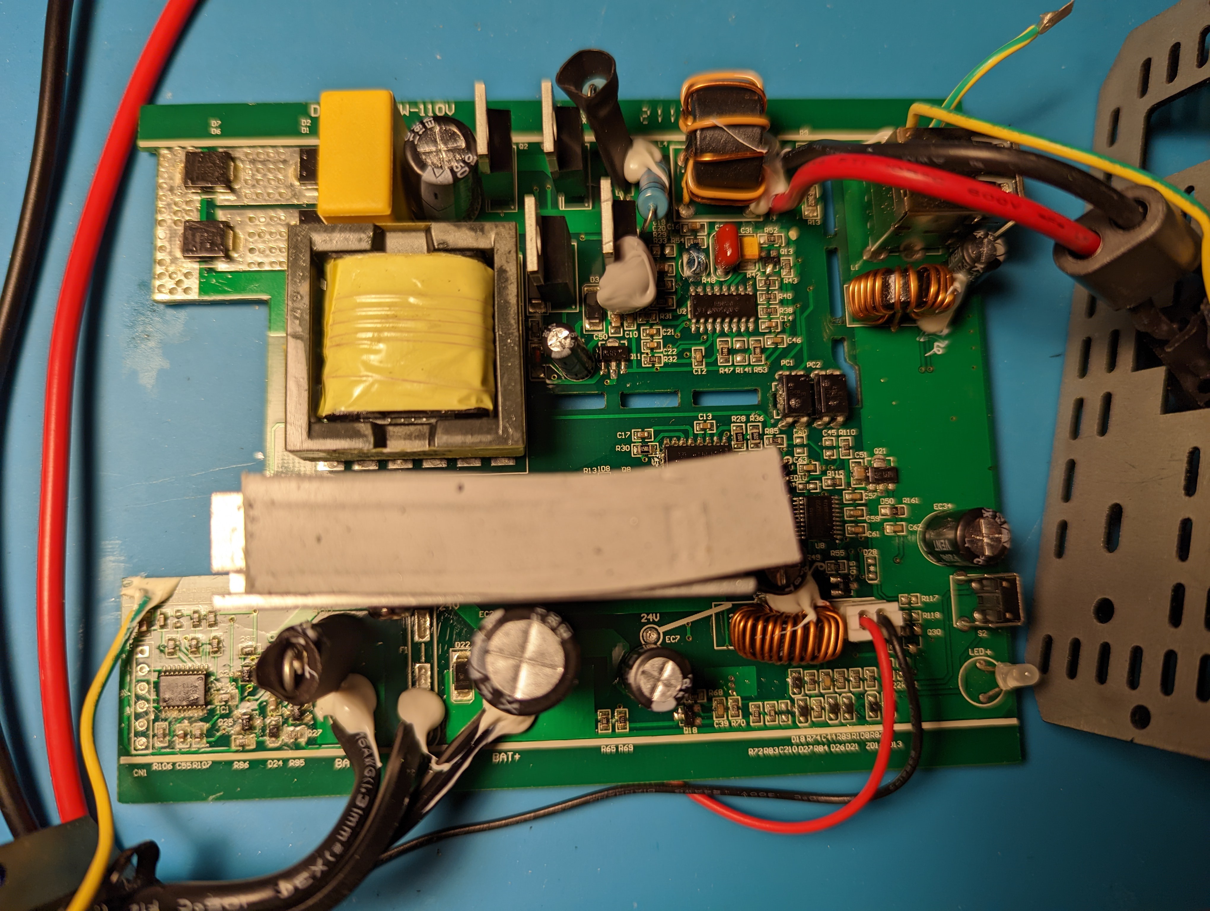
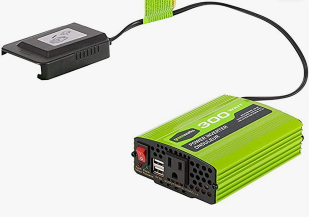
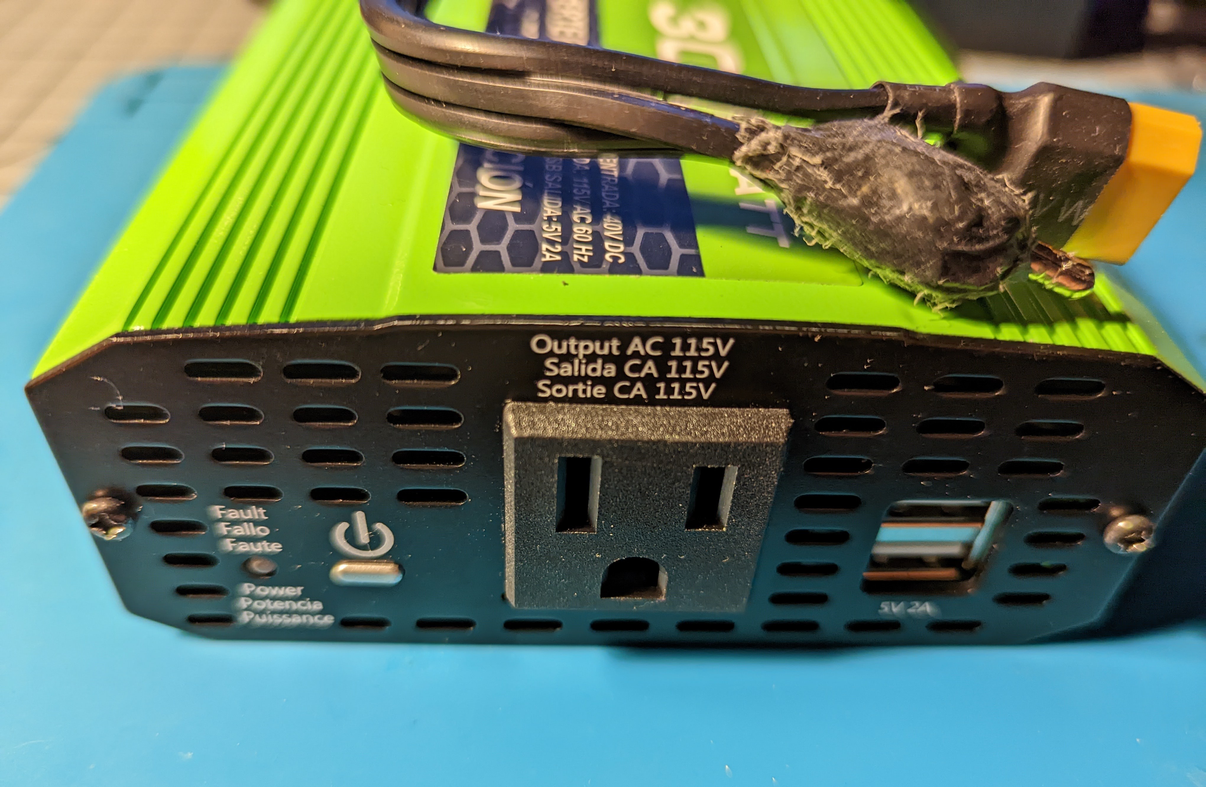
Hacking Greenworks v2 40v Inverter
My adventure with hacking a cheap 36v inverter to work with any 36v battery source.
 Chris Jones
Become a Hackaday.io member
Already have an account? Log in.
Just one more thing
To make the experience fit your profile, pick a username and tell us what interests you.
Pick an awesome username
hackaday.io/
Your profile's URL: hackaday.io/username. Max 25 alphanumeric characters.
Pick a few interests
Projects that share your interests
People that share your interests


 Peter Lyons
 Dixbit
 leadacid44
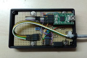
 Christoph
Thanks for the great write up - I just made this modification, successfully!
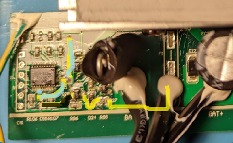
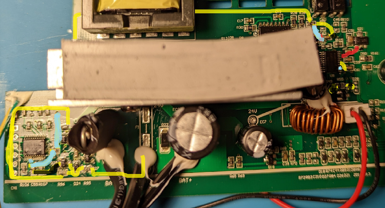
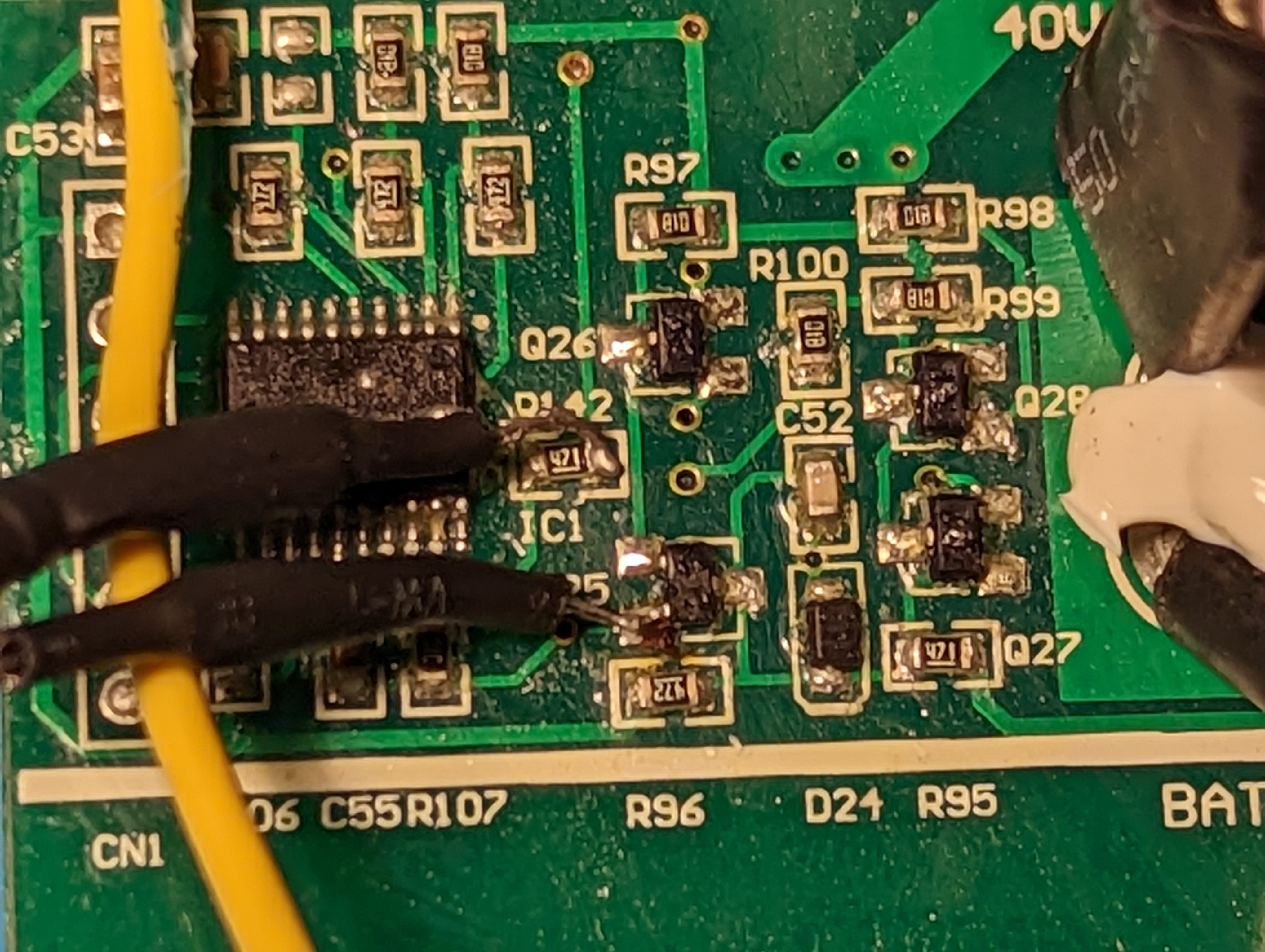
Instead of a THT resistor, I used an 0603 SMD resistor and a short length of 34 AWG enamel wire. This approach has a much lower profile and exerts almost no stress on the junction points.