Close
0%
0%

FLEXTRUDER2 17: Dual drive remote direct extruder

Simple and effective dual drive extruder with a remote motor and flexible shaft transmission

Public Chat
Similar projects worth following
The basis for this design is the idea of using 'standard' drivegears for dual drive extruders, combined as simply as possible with a flexible drive shaft.

Only a worm screw is needed to drive them and get a fair stepper motor ratio. This is the originality of this design and this specific feature is shared with a CC BY-NC-SA license.

All available rollers are made with the same module of 0.5. So we get about 1.3 mm of extrusion per motor revolution for an 8.5 mm nominal diameter roller. This is ideal because a motor full step will produce 0.12 mm of material with a 0.4 nozzle, or 0.08 mm for 0.5. This is small enough to be accurate without pushing the microstepping too far and high enough to get >40 mm/sec of retraction speed. Larger rollers will give nearly the same extrusion rate.

I recycled the shaft and screw from a Flexdrive that wasn't totally satisfying.

Performance is as good as it can be: I won't come back.

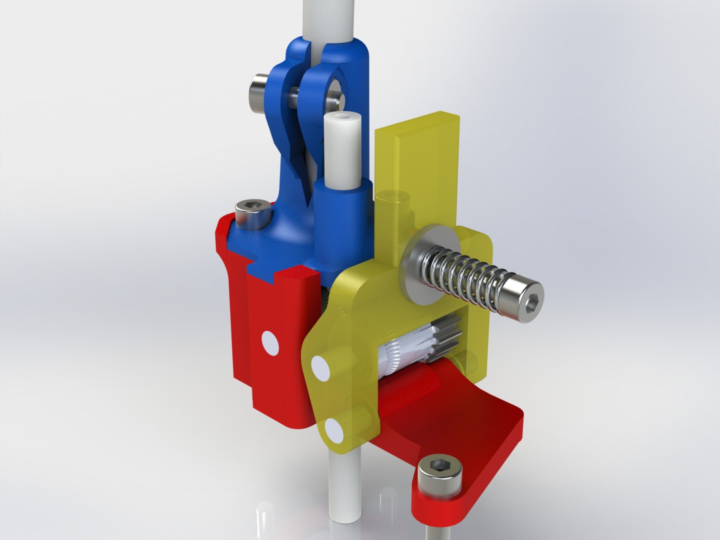
This design is the most compact version based on 17 tooth drive rollers (8.5 mm effective diameter, 14 mm length). ATTENTION you need 3 axles of 3 mm x 23 mm and 4 needle cages K3 5-7... Usually these kits are delivered with only 2 cages and 1 or 2 axles. See Ebay or Aliexpress for these parts. There are also brass worm gears, with different inner diameters. So one can fit another model of flex shafts than the one supplied by Flexdrive or Zesty.

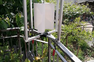
This remote drive extruder is primarily intended for delta printers where the head inertia must be kept to a minimum, but adaptations to other printers is obviously possible. Weight of the complete extruder with screws is 30 grams.

The extruder body can be modified according to the mounting device on the machine. In the basic version, 2 screws of M2.5 X 30 and one of M2.5x 10 are required. It is also possible to secure the flex shaft holder with shorter screws and inserts, if they are not used to also secure the extruder to the head.

The lever is supported by an M3 screw (insert to be fixed in the extruder body). No spring needed.
The filament is guided by a teflon tube inserted on top of the extruder, and a small piece of the same tube goes under the extruder into the cooler... You can extend the teflon up to your filament dryer if you want...

My parameters for Klipper are 1.332 mm/rev, which is 150.12 whole steps per mm of wire.

I was able to adjust the motor parameters (a Nema 17 -23) to reliably get 1500 rpm, so 33 mm/s of retraction speed. The use of a smaller and therefore faster motor is possible, the necessary torque is very limited. Be careful not to program/adjust a too high current on the motor, as this could destroy the plastic worm screw... I'm using around 0.3 A @ 12V for a 4 ohms motor rated 1.5A.

The quality of printing is there... I did not notice any really visible defects related to this device.

Please contact me for any commercial derivative of this concept, or if you want me to design an adapted mount for your printer.

The files are shared under a CC BY-NC-SA license and available on cults or thingiverse.


  • 1 × kit of 17 tooth drivegears (bondtech or clones)
  • 3 × 3 mm axles 23 mm lenght
  • 4 × K3 5-7 needle cages
  • 1 × MR85 ball bearing 2.5 mm height
  • 1 × 685 ball bearing 3 mm height

View all 16 components

  • Flex3drive not responsive...

    Luc JOB12/08/2022 at 22:32 0 comments

    I tried to mail them to be sure that the gears and flexible shaft was still available...

    I had no response for a week now.

    So this open source project has no sense if parts are not available... That's why I have started to re-design the thing with different parts:
    * New worm gear, designed to be manufactured with plastic or metal... Flex3drive allows only plastic.

    * New cable sleeve, for the new gear design

    Now it becomes smaller and easier to print... See the screws? it's M2.5...

    Now I'm in the process of ordering the parts: Flexible shafts with the new sleeve and worm gears.

    Both Flex3drive and Zesty sell the gears + shaft for  $40 to $60... I should be able to be around $30... And less than $50 for the complete hardware kit.

    So that this open-source project doesn't starve by drying of sources before it's really born.

    And for people in need of a finished all-metal product, it's in the pipe...

  • Name changed... S->17

    Luc JOB12/01/2022 at 18:26 0 comments

    For simplicity reason, I decided to rename this version: S is changed to 17 as it is the number of teeth...

    Now there are already many gears available: 17, 18,25,41. So it seems logical to reference the model with the gear size...

    So if I decide to create a commercial version, I can grind 19 to 23 and 26 to 40 tooth gears and change model every year pretending that the new one is definitely better...

    The 18 gear 'G2' style gears are definitely interesting, as the shorter base will make a narrower extruder than the 17....

    And just working on a 'proprietary' worm gear and flexible drive... I find the spare parts of Flexdrive or Zesty a bit on the expensive side, not to mention that they don't sell the worm gear alone.

    So for people that can't recycle their already purchased shafts & worm gears, I might be able to supply soon.

View all 2 project logs

  • 1
    Grab the hardware

    Adapt the mount to the base or the base to the mount before printing the parts.

  • 2
    Finish the parts

    All the holes must be reamed with a drill of the corresponding size. Check the dimensions of your axes to choose the right drill. Using a drill bit of the same size will make all the axes fitting tight, so they won't move alone.

    Use a drill 0.1 mm above the axle diameter to re-drill the base where the lever is rotating, to have some play.

    Check the diameter of both bearing housing, use the tail of a drill. Now you know if your printer is accurate or if you have to tune the filament's flow or slicer parameters.

    Heat set the M3 insert into the base. Take care not to deviate to the filament/teflon tube side. Re-drill the teflon tube housing if needed.

  • 3
    Assembly

    Press the bearings in their housing. 

    Oil the needle cages before inserting into the gears.

    Insert the gear into the mount from the worm gear side. Press the axle when in place. Check if it turns freely.

    Insert the gear into the lever and press the axle.

    Set the lever in place and press its axle. Screw the M3 without tightening.

    Grease slightly the gears and insert the worm gear into the base.

View all 5 instructions

Enjoy this project?

Share

Discussions

Similar Projects

Does this project spark your interest?

Become a member to follow this project and never miss any updates