(this project log is looking like a schizophrenic conversation with myself, bruh)
Project Log 52: 3D modelling Attempt 7.
(I'm previously writting this on a notepad because I'm testing if not creating a project log helps my anxiety. It is ironic how first the project logs drafts helped put me on a hurry to finish it, and now these are a source of anxiety).
__________________________________________________________________________
I wish I had the money and the contact to talk to someone specialized on this thing.
Also, I was really considering making a loan with a bank in order to hire someone and finally finish this stupid project.
Dunno how I would pay the debt, but hey... It is an idea...
A friend of mine suggested me to make a Kickstarter (or similar websites) page with this project... But I tried before, and nobody gave a damn.
I would need a lot of followers and a lot of money to market the project...
I'm really starting to give up on this idea, I'm nowhere near this completion, but I hope I inspire someone more competent than me to make this a real thing...
__________________________________________________________________________
So, the winch mechanism I thought first was to use the same logic as a pulley, where a smaller pulley pulls a bigger pulley. The difference would be that the cable of the winch would be screwed into place onto the pulley.
The problem is that this is a 10:1 ratio pulley-winch, so it would have to make 10 rotations in order to achieve some movement.
It wouldn't be a problem if I didn't think on attaching both sides of the arm to the same screw, instead of moving, it would tentionate the cable, since it can't move.
The simple solution I thought was putting two diferent winches, one for pulling the forearm/limb upwards and another on the opposite side pulling it downwards.
In order to achieve that motion, I thought on connecting both winches with a 1:1 gear ratio, since each gear will naturally rotate to the opposite end, maybe it would avoid such problem.
However, I'm still afraid about the gear's teeth braking due to the loads experienced during use. I don't quite know a possible solution other than use Sprockets, the problem is that sprockets rotate at the same direction.
Maybe I could "solve" that by simply inverting the direction of the winches, one can wind while other unwinds while rotating at the same direction.
And well, as much I made it look like I was completly done with sprockets in general, I think that maybe it wouldn't be much trouble in this case, since the transmission is 1:1 instead of 10:1. :)
Also, I know that one could simply make the rope longer to simply avoid this kind of problem, but I'm just afraid of the energy losses with winches and pulleys.
Winch mechanisms are really, really inneficient due to friction losses with the rope.
__________________________________________________________________________
Also, I was thinking on making the 3D model of the telescopic linear actuators with Stewart platforms like the Hardiman, like I talked about in Project Log 49.
First, I thought on long and telescopic Stewart platforms for each limb, arms, legs and torso.
And maybe add some kind of "elbow", just imagine a tube at the end of the Stewart Platform instead of a simple disk.
The platform would be controlled with both a simulation and simple potentiometers, the idea is basically tell the machine to follow and avoid the position points of the motion capture suit.
Something among these lines:
And a motion capture suit like this one.
Or this one.
So, maybe, it would be easier to control, program and make it work. It could even retract to a small state (since the actuators are telescopic) and be easier to transport.
Not to mention that all the weight would be somewhat distributed to all actuators at once.
I thought this was interesting, it has a lot of range of movements, more than a normal stewart platforms:
__________________________________________________________________________
Also, for some reason pinterest is showing me a lot of images of the anime "86: Eighty Six", which I don't really know the plot, but for some reason people pilot these cool spider mechs because they live in mountainous regions.

(forget the gun on it tho)
I wonder if it would be possible to make it work with reciprocating actuators.
If I'm not being clear, just imagine this velociraptor robot, but instead of being a velociraptor, it is a spider robot:
This other racing octopod is kinda interesting too, and it is more or less the same thing:
I guess it could be possible/useful for each limb/joint to have some kind of elasticity/dampening, so it could adapt to the differences in the terrain without needing too much processing power.
Of course, this is due to its repetitive and almost unchanging cycle of movement.
Maybe one could even use a car transmission on such system? hummm...
"Why you don't use the same system on the exoskeleton/mech suit?"
Good question.
I don't know. :|
I really don't know how to make such system to work in a exosuit or mech... I keep forgetting about trying this out...
Maybe I should at least give a try... On 3D modelling... I guess...
__________________________________________________________________________
You know what? Screw this, i'm going to make the Telescopic Stewart Platform exoskeleton.
It is the most efficient and the simplest one.
There is no reason to make a biomimetic exoskeleton if the entire exoskeleton needs 20 horsepower of energy.
In resume, imagine the following (remember to draw this):
There is a stewart platform, and on top of it, instead of an disk, there is a tube.
The tube will act like a limb, you will be able to put your arm inside the Stewart Platform and the tube itself.
Of course, the Stewart Platform can rotate into directions that could easily break the human body, so it would be wise to put a limiter (like a piece of wood/steel) that blocks the thing from breaking the human body.
Also, one could make the stewart platform stay completly reverted and then put it as its neutral state, so even if it goes against the human body, it will be blocked by its own limits.
(also make a drawing of that)
So, I just noticed that when the Stewart Platform is rotating on its own axis, only half of the actuators actually move, which would mean that I would need the equivalent of twice the power in each limb... At maximum.
Assuming maximum horsepower/watts per limb is +/- 2 horsepower (1800 watts), and that there are 5 limbs, then it would consume in total 10 horsepower or 7500 watts, and since each limb needs twice the value, it would require 20 horsepower or 15,000 watts in total.
... Which is concerning...
Of course, this is the maximum wattage, not that these would be in full wattage all the time... I would say "only half of the legs/arms would use this value per step", but this isn't quite that accurate tho... Between steps you need some effort to put your free leg forward for the next step.
Well, since we have 4 horsepower per joint, I need to divide 3600 watts by 6, or even 9, depending on the type of the stewart platform used.
Which would mean that I need 600 watts per actuator in the case of 6, and 400 watts per actuator in the case of 9.
Well, the problem is that even in these relatively small values, light electric motors and/or drone motors have a *lot* of RPM, meaning that I would need a *lot* of gear reduction for the linear actuators.
... And I really can't find a cheap motor for these values, I'm almost considering putting that 90kv electric motor that I showed in the previous project log...
... Also I think I should give up on the idea of telescopic actuators, because I don't think I would really need *that* much range of movement. And specially because they are too bulky. I mean, one is kinda okay to have, but I need 6 to 9 of these in a single space, which... Can be funky.
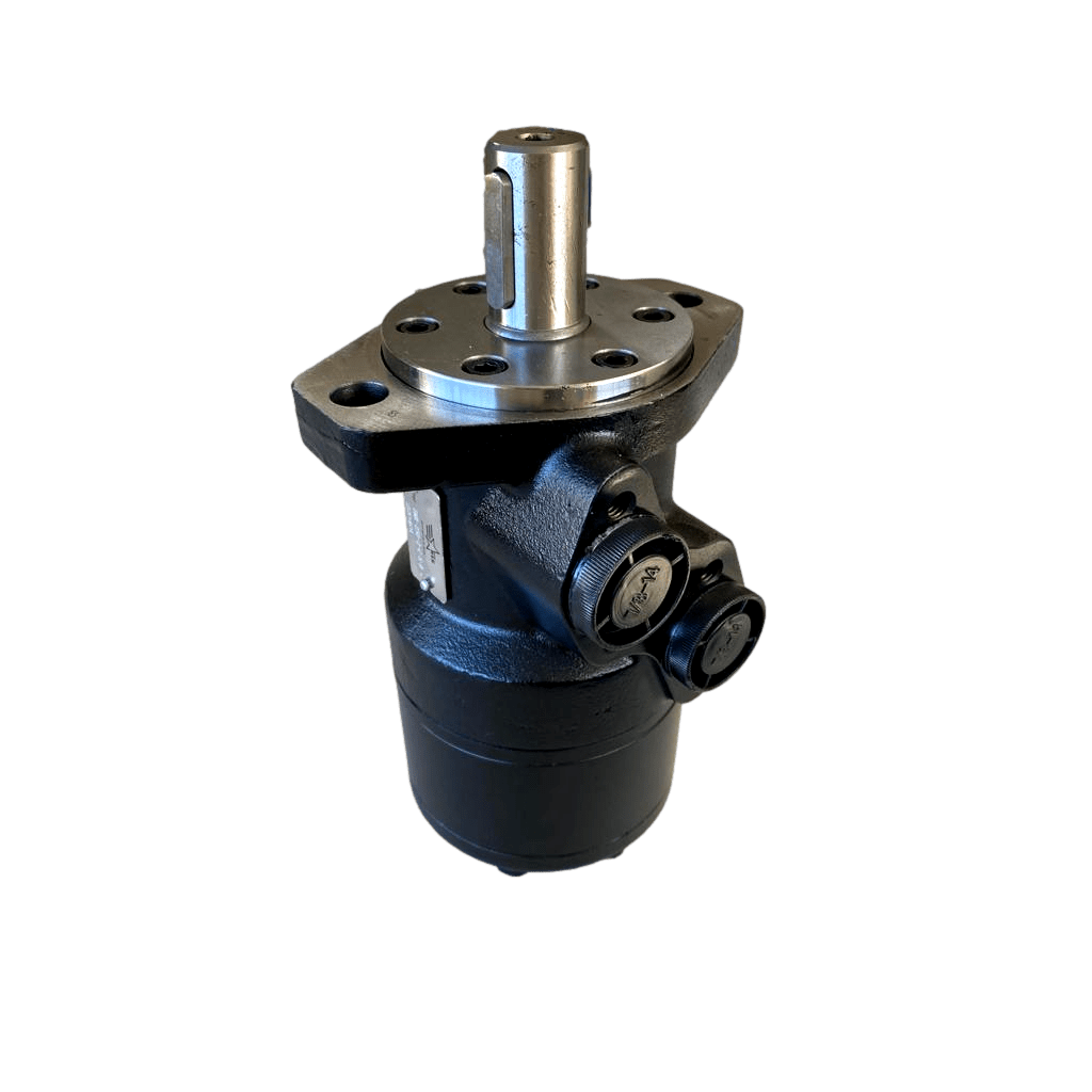
... I Think I should go back to hydraulics in this case, of course, not with 2982389329823 PSI, but something in the middle, like a hydraulic motor that drives the linear motor with a pulley system.
You know, like this thingies, but only one stage, or maybe two.
I say this because it is easier to calculate a rotary hydraulic motor than a linear one.
And the reason is because I don't really think that the gears would actually be able to withstand all the loads on themselves...
But that's just a thought tho...
I mean, I still would do that 10:1 ratio two times with the cycloidal gears and then again with the pulleys/winches.
__________________________________________________________________________
I was looking for hydraulic motors, and more or less, I need 200 newton meters of torque, and the ones that can achieve 400 newton meters are like, 1000 reais (200 dollars).
All of that without gear reduction.
Of course, I can always just copy these machines and so on, but this makes me concerned on how much force these actuators would *actually* be able to withstand...
Well, for what I could calculate, I would need 175 bar of pressure and 2.4 liters per minute for every, and since there is 30 motors, I would need 72 liters per minute, which some hydraulic pumps (more specifically one that costs 550 reais [110 dollars] can achieve) on the cheap would be able to deliver.
The problem is that I would need around 15 horsepower in order to supply the hydraulic pump, not mentioning the hellwork of tubes and pipes I would need to do in order to distribute all the hydraulic oil to every actuator.
Which is a little better than the completly electric one, that would require more or less 20 horsepower in total.
... Which² is weird as heck... How this is using less power than the electric one? I'm missing something?
Also, the hydraulic motors *look* really long, I'm afraid they would just be too bulky, but I asked for more information on the articles I found on the internet.
__________________________________________________________________________
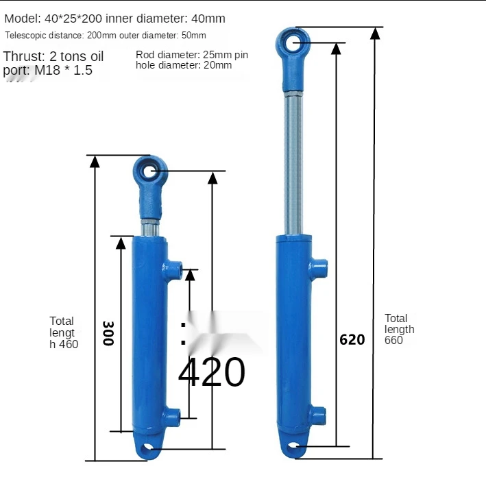
Also, I tested inputing these values on a linear hydraulic cylinder calculator, based on actual hydraulic cylinders for 2 tons of weight, with 175 bar and 2.4 liters per minute and it would achieve 2 tons of weight and take 9 seconds to fully actuate 30 cm of length.
And assuming that it only needs to travel 5cm, it would take around 1.5 to make your arm fully move while the other hydraulic motors would take 0.5 seconds for that.
Hydraulic cylinders are crap (or I'm just bad at math).
Well, I tried again, this time I converted rpm to velocity and torque to force.
The way I did it was just searching on google a rpm to speed converter, lol.
Then, I took the torque calculator and inserted torque and distance before force, which gave me a force of 50,000 newonts (5 tons).
https://www.omnicalculator.com/physics/torque
So, assuming that a 10cm wide axis of rotation of an electric motor or an hydraulic motor rotates at 30 rpm, I would have 15cm per second with a force of 5000 newtons (or 500kg).
So, if I translate that to a hydraulic cylinder, I would have... To deliver 11 liters per minute per cylinder at merely 40 bars of pressure.
Assuming that the 80 liters per minute hydraulic pump supports exactly 8 cylinders per minute, it would require around 3.75 (or 4 to round up) of hydraulic pumps to deliver the necessary fluid flow, and around 16 horsepower to deliver it.
However, if I assume again that the axis of rotation is 1cm of diameter, then this would change to: 1.5cm per second and 5 tons of force.
Which would need 1.4 liters per minute per cylinder and 157 bars of pressure, which would require around 42 liters per minute in total and around 13 horsepower (9750 watts) of power.
Which makes me think that maybe the previous calculation of merely 15 horsepower may be wrong, since it needs a lot of torque also... I *think*, I asked some sellers and they just say "15 horsepower is enough to make it work" in a general manner... Not saying they are lying, they simply may not understand their products as much as the clients.
Dunno about the EUA but here in brazil, sometimes you need to be extra sure to ask/talk to sellers because some times they literally don't know what they are selling, so just say things like: "sorry pal, it is just written 12 volts on this electric motor, dunno what 'watts' and 'brushless motor' means tho".
__________________________________________________________________________
Alright, I wasn't still convinced on giving up on direct electric motor with gearbox in order to go to hydraulic cylinders. So I asked around.
... And the answer is no.
You see, in my innocence I completly missed the point (as always [god, if I was an actual engineer student, so much trouble could have been avoided, dang]), if the torque is 500 newton meters, then converting it to other units would give 5000 kg of force per centimeter.
Needless to say, even steel wouldn't be able to withstand such massive weight in a mere 1cm radius pin, don't you think?
Well, while I was writing this I thought the final result would require some crazy stuff, like a bar with 40cm of diameter or something.
But some people suggested that I would need only 3 to 8 cm of diameter :|
__________________________________________________________________________
Also, I found *another* problem: the length of said hydraulic pistons. The one I found would have 46 cm of length *unactuated*.
They are *too* long (hehe) and wouldn't allow for full body movement.
I was thinking that telescopic actuators would be "the only way" of making this new system possible, but I was super duper wrong. A simple short linear actuator system is more than enough.
__________________________________________________________________________
Well, just now I noticed that I've made a mistake (AGAAAAAAAAAAAAAAAAAAAAAAAaaaaAAAAAAAAAAAAAAAAAin), I don't need 500 newton meters per actuator, because that's the 1800 watts torque in total, not the 600 watts per actuator.
So, yeah, I basically calculated a exosuit that lifted 5 tons per actuator, just the legs would be able to lift 30 tons each. :|
It would 1cm per second, but still 60 tons.
Did I f8cking made a viable exosuit/mech that can lift 60 tons by f8cking ACCIDENT...? :|
I'm so confused. I hate myself. I need a fricking engineer to help me out, for gods sake.

Ok, I don't need 5 tons, I just need 1/3 of that (1800watts/3 = 600 watts), so I would need around 2000kg of force or 200kg force if it was at a 10cm radius.
Well, with the new specifications, I would run in a similar problem to the previous one: liters per minute.
If I was to convert the 10cm radius of the winch/pulley mechanism, I would have around 15cm per second, which would require 11 liters per minute for all actuators, and since there are 30 of them, I would require 330 liters per minute, 3 pumps at 15 horsepower, around 45 horsepower in total.
If we take at best 3 cm per second, then I would need 3.7 liters per minute, which would give around 100 liters per minute at 15 horsepower, which is possible, but barely fast enough to fill every actuator.
Also, I would probably just be able to slowly walk (I think).
So... Since I don't need *that* insane amount of power in total, I think it is safe to say that instead I should keep up with the electric ones.
Of course, I could just put wheels on it and make a mech, but let's make it an exoskeleton first, shall we? :)
Now I'm actually excited! After all, Mechsuits are *probably* viable. :)
__________________________________________________________________________
Actually, I was looking here, and I think it could be a good idea to use the 5 ton hydraulic cylinders instead of the 2ton ones, but only using the 5 tons for maximum 2 tons.
I say this because the pressure required to make a 5 ton hydraulic cylinder to lift 2 tons is "only" 60 bar, around 6 MPa.
I would need 5.6 liters per minute per actuator, but I would only use around 5 horsepower for such pressure.
I would need around 168 liters per minute for every actuator, but again, I could use another hydraulic pump with 5 horsepower and stay at 10 horsepower in total instead of 15 or 45.
Also, this could mean that the composite material that I will use won't be put in its limit all the time.
I tried to check the energy required for a 10 ton hydraulic cylinder with less pressure in order to lift 2 tons at same speed, but even then it would use around 10 horsepower to feed 14 liters per minute for every actuator (420 liters per minute in total), although it would only need around 25 bar of pressure.
... Wait, what if I used the 10 ton hydraulic cylinder for lifting 5 tons in an *actual mech* instead of the exosuit?
I would need around 9 liters per minute for 3cm per second and 100 bars of pressure, this would be 270 liters per minute, which I would need around 2 to 3 pumps with 10 horsepower each, giving 30 horsepower in total.
If it was 2 tons instead, it would be around 40 bars of pressure.
I was also thinking on making hydraulic accumulators, since you obviously wouldn't need that much force on the arms, probably on the legs only.
__________________________________________________________________________
Also, kinda made a mockup of the linear actuators (a paper tube) just to see if my body would have enough freedom of movement to move and well, it mostly okay, unless I try to touch my own shoulders with the oposing arms. Basically, unless I make a telescopic actuator in the chest, the structure of the actuator won't allow me to do that.
__________________________________________________________________________
Also², I'm starting to regret even considering using hydraulics, because bruh... How I will fit so many hoses, variable controls, oil and a combustion engine in this thing...?
__________________________________________________________________________
Also, bad news: the pulley drive system logic doesn't work for pulley mechanisms.
Basically. I was thinking on using the compound pulley mechanism to make the linear actuator, but it only works by the number of pulleys that these kinds of systems have.
So this winch driving a compound pulley mechanism that lifts a weight, in this case, a linear actuator, will only have a 2:1 reduction ratio.
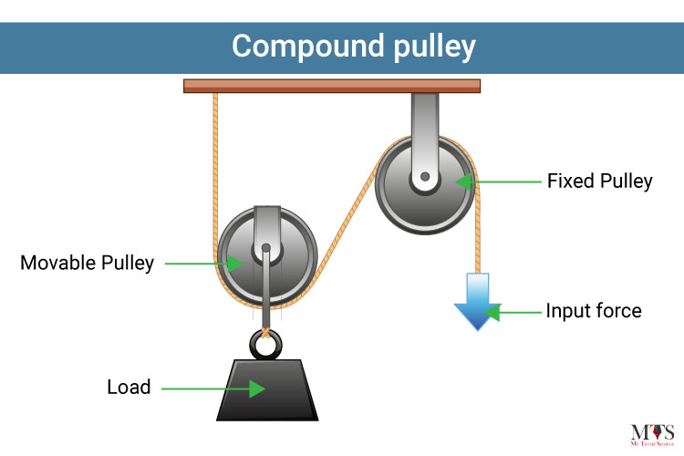
Now I have to figure out how to make this damn thing work properly.

Every pulley you see in the image loses 5% to 10% efficiency. :|
But comparing to my system, this looks like the 1:6 reduction ratio version.
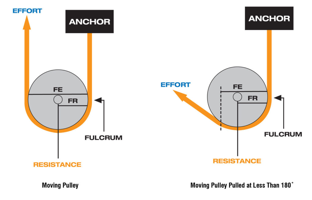
There is also this picture showing that pulleys have fulcrums and mechanical advantages.
I think I would need to make a conventional reduction mechanism, with a small input driving a bigger input slower, but stronger.
I was thinking on actually a winch, although winches have limited travel, I could "just" make the length of the winch longer enough to allow the full actuation of the system.
Also, I will put a crapton of lubricant is these goddang pulleys, because, gawd, These will definitely need it...
__________________________________________________________________________
I was watching this video and it made my question (again) if I really shouldn't change to hydraulics, because the plastic gearbox simply exploded with "mere" 50 newton meters of torque, I will be using 4 times that value on each actuator...
So, the guy didn't care about efficiency too much, because that wasn't his objective after all. But you can see from time 0:54 that the final torque should be around 200 newton meters.
However, he only achieved around 50 newton meters, so just by the torque alone you can see he already lost 75% of the energy during the process.
Of course, I'm not using his gearbox, I settled for using the James Bruton cycloidal gearbox with 10:1 ratio that seems to be more solid, and I will also use a winch mechanism with also 10:1 ratio.
But I can't help but feel like I'm missing something in this process...
__________________________________________________________________________
This is me from the future, the fact I was missing is that by making the diameter of the winch/hoist/pulley mechanism, it loses 10 times its force.
So it wouldn't lift 30 tons or 60 tons, each actuator would have 200kg of force, so 1200kg per actuator in total, and with the mechanical loss from being at 1/3 of the distance, I would be able to lift 400 kg.
Of course, if I go back to 1-3 cm per second of speed instead of 11cm per second, then it would in fact, be that strong.
__________________________________________________________________________
Anyway, I will try to draw this fricking mechanism.

Well, anyway, I will try to explain this crap.
On the left, you have the initial idea: a 1cm diameter winch pulls a 10cm diameter winch that is directly attached to the linear actuator.
On the right, you have a 2cm diamter winch pulling a 20cm diameter winch with a inner winch with 10cm diameter.
The bottom winch/pulley is where the electric motor will be attached and drive the winch.
I had the idea of doing that for two reasons:
1- mechanical advantage
2- the linear speed is directly proportional to the diamter of the driven actuator.
This way, even though the actuator on the right has a 10:1 reduction ratio, the winch that will pull the mechanism will have 10cm of diameter, and thus, 15cm per second of speed, which is a lot, and on top of that, the motor drive will have a mechanical advantage of 2 times (supposedly).
But I'm concerned on the actual final result, I'm concerned that by applying the 10cm diameter winch with the 2:1 mechanical advantage will affect the speed and torque of the linear actuator.
__________________________________________________________________________
One interesting finding I got was double action telescopic hydraulic cylinders.
Hydraulic cylinders normally are double or single action (there are other types, like triple action, for some reason), telescopic cylinders on the other hand, are normally single action, because it is simpler to do it like that.
But one interesting thing about double action telescopic hydraulic cylinders is that the piston head has a hole on it (obviously, so the other stages can work), but you can actually make the area of the hollow piston heads so it matches the area of the retracting action, unlike conventional hydraulic cylinders, where the rectraction is often really weaker than the stroke.
Of course, *depending on the design*.
The only problem I could think of was the insane amount of fluid flow this dang thing would need...
... Unless I make a telescopic "filling" tube that would occupy space and thus, require less fluid for the overall system.
__________________________________________________________________________
In any form, unfortunately I will be forced to stay with the hydraulic thingie.
Because each actuator costs 300 reais (60 dollars)... And I need 30 of these. :|
And for the life of me, I can't fricking find UHMWPE (ultra high molecular weight polyethylene) on granules and so on, neither I can find UHMWPE trash plastic so I can melt on useful stuff.
So I think I will have to stay with HDPE (High Density Polyethylene).
... And now that I'm here, I never cared to search for the properties of HDPE and compare to UHMWPE, I thought that UHWMPE would instantly be better than HDPE, but it quite the opposite, as far as I looked into it.
Also, I found out that some HDPE composites mix not just this plastic with fibre-glass, but also talc for some reason?
https://www.ncbi.nlm.nih.gov/pmc/articles/PMC5452666/
I didn't read yet, but... I would say that they use it because talc is a reeeeally fine powder. For what I remember, if you mix any kind of reeeally fine powder with super glue, such as graphite and even cinnamon powder, it becomes some kind of super strong solid/composite material.
__________________________________________________________________________
Acthually, I don't even know where to start with hydraulics.
Yes I had the *intent* of copying everything with a homemade version... But is that even possible? Or even worth the trouble?
How I'm going to disassemble a hydraulic cylinder piston in order to make a mold and then a copy out of HDPE?

How the heck do I disassemble one of these?
I was thinking on buying one of these from aliexpres, they "only" cost around 800-1000 reais (160-200 dollars) with shipment fee.
Let's try to list the stuff I would need for the hydraulic mech/exosuit and compare to the electric mech/exosuit:
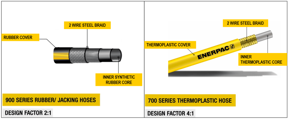
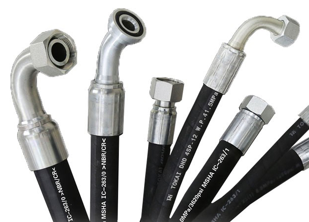
1- Hydraulic hoses or hydraulic tubes: these cost hundreds if not thousands of reais (200 dollars or more).
2- Check valves: these also costs a lot, specially for high pressure cases.
3- Progressive valves: I need these in order to put the servo motors in order to open and close based on the pilot's movements.
4- Pressure limiters: if I want a progressive amount of force to be applied, like an electric motor's torque, I would need these.
5- Hydraulic accumulators: these cost thousands of brazilian bucks, and are really dangerous.
6- Hydraulic pumps: cost 800 to 1000 reais (160 to 200 dollars).
7- combustion engine: cost thousands of reais.
8- Arduino board controllers for servos: are kinda cheap actually.
9- Efficiency, although you can find some pump designs that have 80% efficiency, it doesn't mean the system will be that efficient (https://www.fluidpowerworld.com/hydraulic-efficiency-myth/).
Not to mention that the hydraulic fluid may reach high temperatures because of the fluid dynamics in a hydraulic system, temperatures high enough to melt HDPE, hundreds of degree celsius.
(maybe I could control the valves with manual input of my own body, but it is hard to say if it would work with stewart platforms).
I would need a spare part for every little thing, or I would need to actually buy everything and then attempt on copying everything with HDPE injection molds. I think it is not really viable...
Yes, I *could* build everything from the ground up without the need for buying originals... But I'm reall qualified for that? *hyphotetically*, the only cost would the HDPE, the pump, and other materials for making composites, like fibreglass, carbon fiber, aramid/kevlar fiber or plain steel wire for reinforcement.
Now electric mech/exosuit:
1- Electric motors: costs 300 reais (60 dollars) each, some times much more than that.
2- ESC controller: around 50 reais to 100 reais (10 to 20 dollars).
3- Arduino processing boards.
4- 6 ton resistant rope: a few hundred reais for a 100 meters or so.
5- Laser cutting master pieces for HDPE molding.
6- Sensors: these may be cheap (around 5 to 10 dollars), but since I need some for every actuator, it can hurt the wallet when bought on bulk.
7- Power source: a combustion generator or a homemade hydrogen fuel cell.
Now that I compare each... I guess the electric mech/suit wins...
(how much you bet I will suddenly change my mind and choose hydraulics?)
__________________________________________________________________________
(I already changed).
I couldn't find any website that was selling these kinds of electric motors on bulk, so the shipment fee was around 2000 reais (400 dollars) and the final price of every single motor (that costed 367 reais [74 dollars]) was around 11000 reais (2240,25 dollars).
I was thinking on 3D printing or laser cutting models on styrofoam or similar materials and then casting an HDPE copy.
Of course, the 3D printing process won't have nearly as much precision necessary for building this thing.
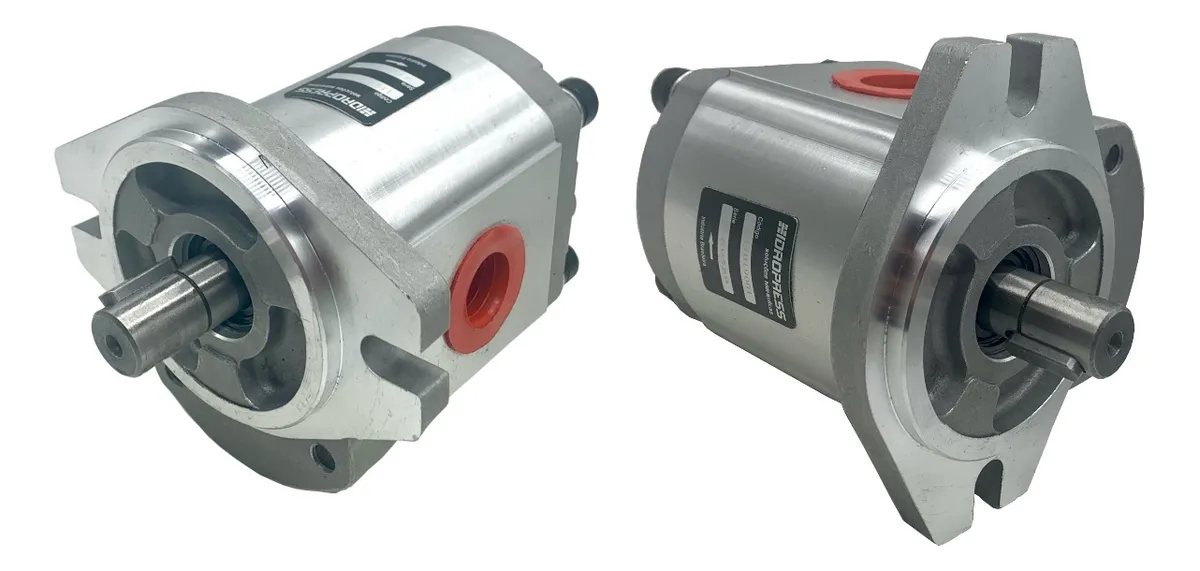
The positive part of this is that some hydraulic components (such as the gear pump) are basically flat images, perfect for laser cutting.
... I was wondering if this is not a coincidence tho... A lot of gear pumps in the market really look like a casted piece, and it would make a lot of sense...
Also... I think this could bring me a lot of freedom on designing the components for the hydraulic system... But I don't think it would be beneficial for me that much, after all, i'm not an engineer.
Also, I took a while searching 3D models of hydraulic pumps and cylinders, but... Couldn't I just copy hydraulic motors and keep the same damn design of the electric system?
I mean, the hydraulic motors would be easier to make than the hydraulic cylinders...
Well, this is me from the future: bad news, no matter how much I search, winch mechanisms are like, 15% efficient. So what is even the point of using electric or hydraulic motors in this systems?
This is me from the further future: I just saw that this kind of mechanism isn't a "winch", but a "hoist", and hoists have 95% of efficiency.
An answer someone gave to me: "Winches used to lift are typically referred to as Hoists, and there's a lot to them since we've recognized that large weights in the air will kill you if they fall on or near you. This is really not a DIY type of device."
Well, luckily I'm building a mechsuit, not a winch, I will just stay on top of it. It will definitely be safe... /s
Also, I forgor to say, but if you put another winch/hoist on the basis of linear winch/hoist mechanism that I previously showed, connected to another inner linear actuator, you will actually have a telescoping mechanism.
Not so dissimilar from this:
Which would be very handy, since
(I accidentally erased the rest of this part, and I don't remember what it was written, lol)
I guess I would say something like "which is handy, since you could make telescopic ones easily"...
__________________________________________________________________________
Also, I was thinking here and one thing that stood out is that one of the reasons hydraulics aren't that efficient is due to the mechanical losses on the hydraulic fluid flow.
I don't know how much high these losses are, but I would need to make as little curves as possible.
The ideal hydraulic pipe would be a straight pipe directly connected to the machine in question, however, I do have some ideas on how to achieve this.
1- I either use straight pipes until it is impossible (like a curve or something), then I put the hydraulic hoses with as little curves as possible connected to the actuator.
2- Other option is tho literally use straight pipes everywhere with curves as wide as possible in order to not mess the flow.
For example, I thought on a tube connected to a hollow sphere joint that connects to another hollow isphere joint on the actuator in question.
Or simply divide itself in a star-tube with telescopic tubes connecting to the actuators with also hollow sphere joints.
Of course, this in the case of the mech.
I think I might need to draw this...
Also, I believe I will have to put the valves (of any kind) closer to the actuators, on on the actuators themselves, since these cause a significant amount of turbulence.
In both cases, I'm getting a little concerned, because if the mech suit falls into the ground... A lot of stuff may break...
__________________________________________________________________________
Also, with the heat issue of the hydraulics I was thinking on mixing teflon powder with graphite/graphene powder in order to increase its heat resistance, but that can fire backwards since teflon has a terrible stiffness.
I could also add other plastics, such as Nylon, Polycarbonate, ABS, PEEK (Polyether Ether Ketone) and so on.
I choose HDPE because it is simply a common plastic to find everywhere, specially on trash.
Also, I totally forgor about fiber glass, steel, even Alumina or Silicon Carbide powder and so on.
Also², I forgot that there are 3d print filaments on sale on the internet, I can just buy these filaments and cut them down.
When I bought my 3D printer I also bought a polycarbonate filament roll, I barely used it.
Except PEEK (Polyether Ether Ketone), just 500grams of this crap costs 2000 reais (400 dollars).
Although I will have to research a little more on the internet, because I feel like if I put so much crap on this polymer structure, it will make the final product peform poorly.
Also, I was searching here and there are two kinds of hydraulic systems: open loop and closed loop.
I intend on using open loop in either way, but the closed loop is the one that needs active cooling since it *actually* can reach hundreds of degree Celsius.
"Hydraulic fluid temperatures above 180°F (82°C) damage most seal compounds and accelerate degradation of the oil. While the operation of any hydraulic system at temperatures above 180°F should be avoided, fluid temperature is too high when viscosity falls below the optimum value for the hydraulic system's components.
To achieve stable fluid temperature, a hydraulic system’s capacity to dissipate heat must exceed its heat load. For example, a system with continuous input power of 100 kW and an efficiency of 80 percent needs to be capable of dissipating a heat load of at least 20 kW. Assuming this system has a designed cooling capacity of 25 kW, anything that increases heat load above 25 kW or reduces the cooling system’s capacity below 25 kW will cause the system to overheat."
Source: https://www.machinerylubrication.com/Read/680/hydraulic-overheating#:~:text=Hydraulic%20fluid%20temperatures%20above%20180,for%20the%20hydraulic%20system's%20components.
__________________________________________________________________________
... Wait, what if I try copying the brushless electric motor?
I know that I can't find the specific materials used on the metal cores or what type of magnet was used on the rotor... But I could copy these, right...?
_____________________________________________________________________
Edit¹:
I just found this 3D model on GrabCad with this exact Brushless motor with 90KV that I'm thinking on using.
I think I won't need to buy one and then disassemble it, but it is a nice option.
_____________________________________________________________________
A little bit easier than copying the hydraulic pumps, valves, cylinders, hoses and so on...
I think I should do that instead...
Well, I will at least try to see if it is at least feasible.
In this video he teaches a really interesting way of cutting fine metal plates on the shapes you want.
Basically, you cover the sheet metal with protective paint and uses a laser engraver (or other method) to cut the protective layer of paint. Then you submerge the metal plate on a bath of salt water with a electric charge from a battery and the salt will slowly rust and eat the unprotected parts of the steel plate, giving you the shape you want.
That is relevant for a electric motor because I will have to find a way of making a *lot* of plates for the stator part of the electric brushless motor.
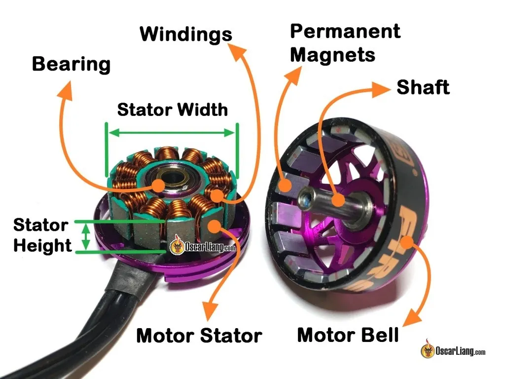
... THe only problem is that I will probably need to disassemble and k1ll the 367 bucks electric motor, ugh...
Well, from the images, the Stator has 36 "teeths" (or poles) and accordingly to its dimensions something between 7 and 8 centimeters of diameter.
Well, on the internet these stators cost more than the brushless motor itself, lol.
... But maybe I could find better types of metal for stators... And maybe better magnets, such as neodymium magnets (if these aren't that expensive).
... I was wondering, would it be efficient to make the stator this weird star thingie, or just put electromagnets on its place? It would be easier to produce manually...
The video below isn't quite relevant to this subject, but I'm just putting here in order to remember about it, he order a bunch of sheet metal cuts form the internet in the cheap, so I will try to do the same.
I was looking around and I received this answer (that was copy-pasted from ChatGPT):
"Soft Magnetic Composites (SMCs): SMCs are composite materials made of iron powder particles embedded in an insulating matrix. They offer good magnetic properties and can be shaped into complex geometries. SMCs can provide an alternative to silicon steel, particularly in applications where reducing eddy current losses is essential.
Compared to traditional silicon steel, SMCs offer several advantages:
Reduced Eddy Current Losses: Eddy currents are induced currents that circulate within conductive materials, leading to energy losses. In SMCs, the non-conductive matrix between the ferromagnetic particles helps to reduce eddy current losses, resulting in lower core losses compared to silicon steel. This improved performance is particularly noticeable at higher frequencies.
Design Flexibility: SMCs can be formed into complex shapes and have the potential for intricate geometries that are challenging to achieve with laminated silicon steel. This flexibility allows for more efficient designs, reduced manufacturing complexity, and improved utilization of the available space within the stator.
Vibration Damping: SMCs exhibit good damping properties due to the presence of the polymer matrix. This helps reduce noise and vibration levels, resulting in quieter motor operation.
However, SMCs also have some limitations:
Lower Saturation Flux Density: SMCs typically have lower saturation flux density compared to silicon steel, which means they may not be as suitable for high-flux applications.
Lower Permeability: The permeability of SMCs is generally lower than that of silicon steel. While this can result in reduced core losses, it may require more material volume to achieve the same magnetic performance."
This seems like a good alternative to laminates since I don't have the tools for that, of course, at the cost of some efficiency that may or may not be compensated by the neodymium magnets (if I even have the money for that).
I also found some ads online selling silicon steel for transformers, around 100 brazilian bucks (20 dollars), but these come in the shape of an "E" or an "l", not really in the shape that I need, but I can simply cut them with a scissor.
Nah, for this price, it comes too little units to make 30 motors.
However, I'm literally looking for *anything* containing silicon, pure iron, nickel, crome and cobalt.
Brute silicon metal that I will try to break/cut to smiderings, nickel/crome/cobalt electrodes for welding, iron foils to be cut, old transformers and so on.
I will cut everything to pieces in order to make these SMC cores
I was wondering here: if I can make the electric motor from scratch, what if I change the wire thickness?
You see, the thicker the emaneled copper wire is, the more amperage it can transmit, and the more amperage it can transmit, the bigger the torque output, so I could make a 30 rpm electric motor without much trouble...
Except that I would probably overheat the entire thing and possibly even brake it.
__________________________________________________________________________
Well, I was thinking here that since I'm making linear actuators with hoists/winchs, I would need a manner of avoiding the tube/square thing that will move from pressing too hard on the walls/bearings of one side instead of the another.
The best way of avoiding this would be putting an actuator on both sides, or even more, and thus, it could make sense to use multiple smaller electric motors instead of just one (that costs 365 reais [+/- 65 dollars]).
I will try to find electric motors suitable for such thing and then I will analyze if it will be worth the trouble.
... Well, it is me from the future, and boi, oh boi, I can't believe how many electric motors out there with 20watts are more expensive than this stupid thing.
Bruh, I literally came across an electric motor with 0.2 watts that cost twice as much as this 90kv thing.
I found this 180watts electric motor that has 40,000 RPM, if you divide 600watts per actuator by 4, you would need 150watts per actuator, needing 120 in total.
If you multiply the price tag 33,88 reais (6,88 dollars) by 120, one would need to pay 4065.6 reais (820 dollars), *not including the goddamn shippment fee, that is as expensive as the electric motor itself; costing 8000 reais in total (1640 dollars).
I'm starting to feel more compelling to switch over to hydraulics, because there is no way that I would be able to afford this electrical thing...
Even if I powered it up using a 20+ horsepower brushless motor (or induction motor), it would still cost way less than fully electric.
A 25kw (33 horsepower) electric motor costs 3000 reais (600 dollars) on ebay...
Copying the electric motor with SMC's is still a possibility tho.
__________________________________________________________________________
Waaaaait a Mcfricking minute.
I am the stupidest person alive?!
If one Stewart Platform of this mech with 3600 watts would be able to lift around 12,000 kg (supposedly), this doesn't mean that I would just need to make a stewart platform 100 times less powerful?
Meaning that I wouldn't need 600 watts per motor, but just 6?
This means that an exoskeleton with 6 watts would be able to lift 40kg.
I mean, assuming that each actuator is at a distance of 1/3 of the fulcrum point compared to the arm, then the actual mech would be able to lift 400 kg.
Of course, in mechanical lever logic, but for some reason it feels like the mechanical lever and torque have completly different logics for me, and it is all really confusing...
So... Since 1 newton meter is 10kgfcm, and assuming that the disk of the hoist mechanism has 10cm of diameter, then this would be able to lift 1kg, so I need 10 times more force, so 10Nm, but since I will be at 1/3 of the length of the mechanical lever (aka limb), I would need 3 times more power, and thus, 30 newton meters and 30 RPM in total.
Resulting in 94.25 watts.
Dividing this by the 6 actuaros, and since only three will working when rotating, then it would be more or less 30 watts per actuator.
So, 200 watts per limb and 1000 watts in total.
I guess this is more doable...
Of course, I'm assuming 200 watts in total, but in reality, it would only be 100 watts, the same applies to the mech.
So, it would be 500 watts/0.6 horsepower for the exoskeleton and 9000 watts for the mech, 12 horsepower in total.
Now I just noticed something...
And it may or may not mean that I misscalculated stuff (again), but it doesn't look weird that an exoskeleton with 0.6 horsepower can lift 100 kg, but a mech with 20 times more power (20x0.6=12) can *only lift 4 times* more weight?
Yeah, I misscalculated something, I don't need 300kgfcm (30 newton meter), I need 3000kgfcm (300 newton meters) of torque because the disk has 10cm, so it is 10 times less torque.
So it would be 900 watts of power in total per limb, not 90 watts, meaning it would be 4500 watts in total, 6 horsepower.
The same applies to the mech, it would be able to lift 200 kg at the arms, not 400, neither 4000, neither 12000 (assuming that it uses the 10cm wide winch/hoist/pulley, the calculations where it was 1 to 3 cm per second are correct, I think).
So, in order to lift 1000 kg, I would need 10 times more power, around 120 horsepower.
The mech is still viable *if* I make it to move 1 cm at second.
__________________________________________________________________________
Holy crap my dude!
I was all excited looking for 30-50 watts electric motors and these are more expensive than the 365 reais (65 dollars)!
How in tarnation these smaller motors are more expensive than a brushless motor?!
However, I did find a *single* electric motor with 25 to 30 wattage of potency, and it looks like one of those motors you find on PS2 controllers.
It would cost around 500 reais (+/- 100 dollars) in total for all 30 actuators, but even then, I would lose some power with the power transmission. I would need a 50watt one.
At the end of the day it is more cost effective to buy a 300 brazilian bucks brushless motor and copy it than buy properly rated electric motors.
This is such bs...
__________________________________________________________________________
Anyway, all this talk and I didn't 3D modelled crap.

(you guys have no idea on how long I've been procrastinating, for some reason, every time I think on actually 3D modelling, I feel a spike of ansiety through my chest and an annoying voice saying that it is not worth and I should just give up)
__________________________________________________________________________
Well, my last project log was 28 of may, so it has been 11 days since then (the moment I'm writting this), 3 more days for 2 weeks.
Also, I think it is the "birthday" of 6 months of me working on this stupid project.
Half a year has passed and almost no progress on this crap... Sigh...

__________________________________________________________________________
I was trying making this 3d model thing on Blender again and again, but no matter what I tried, it was never going as I expected.
3D modelling programs always have confusig ways of moving and changing the goddamn 3d model.
If I could simply take the 3D model with my hands and put it where I want, I wouldn't have half of the problems I have with 3D models...

Well, here is a drawing instead of a 3D model.
However, I will try to make the 3D model of the actuator later, right now I'm having some personal problems...
Discussions
Become a Hackaday.io Member
Create an account to leave a comment. Already have an account? Log In.