 Sam Ettinger
Like many good projects, this started with a prank tweet:

Understandably, I got sucked into hypotheticals, wondering what it would take to make one of these IRL. Some 0201-sized LEDs in a 7-segment arrangement could fit in an 0805-ish footprint, right?
Experiment 1: a 6-pin module in an 0806 footprint
If we use a single 0201 LED for each segment of the display, we can fit this onto a space a little wider than a standard 0805 SMD footprint. With the LEDs arranged in this fashion, it should be possible to light up any one segment while connected to 6 digital I/O pins:
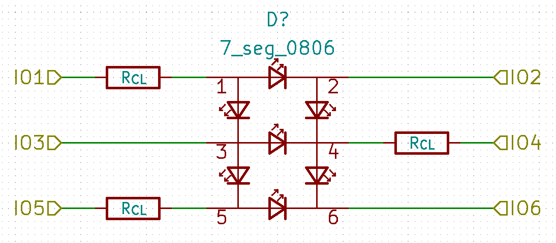
(Those current-limiting resistors aren't part of the 7-segment module; they're just there to demonstrate that I need 3 current-limiting resistors per digit.)
You can't just order an 0806-sized PCB from most fab houses, though, so I had to get creative with my flex PCB order...
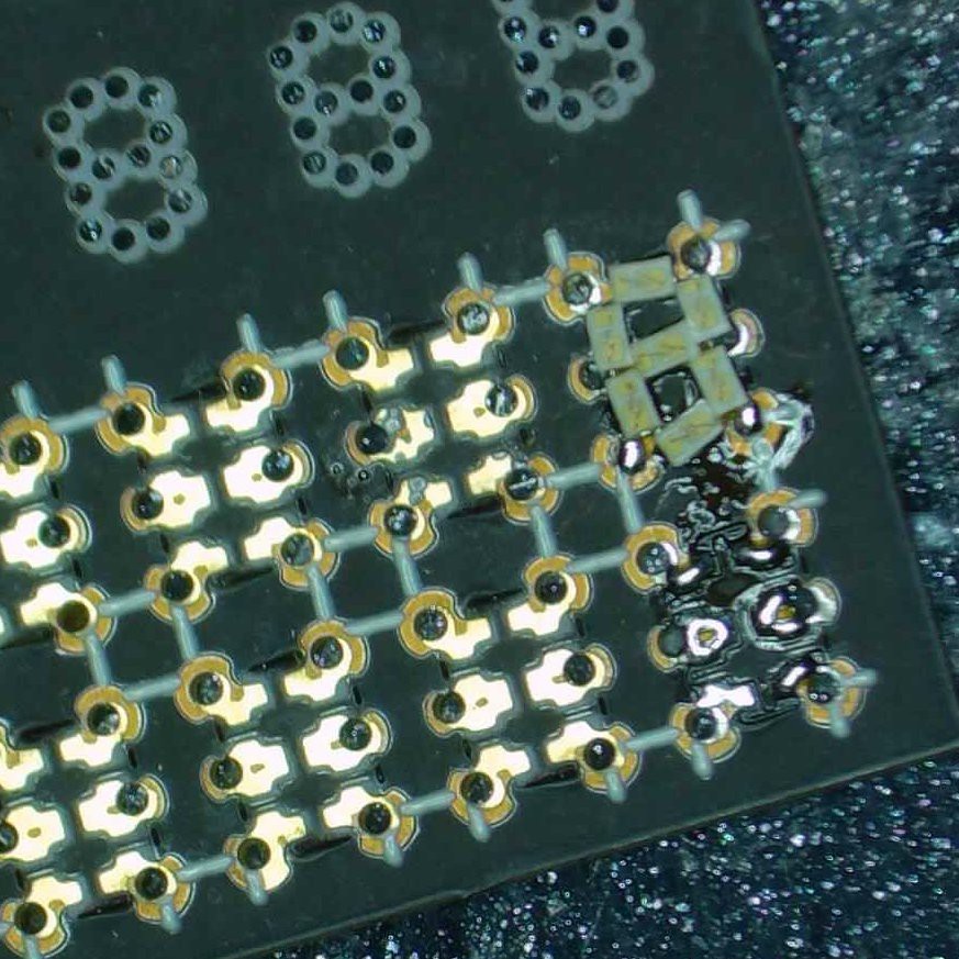
This is in project "6pin_7seg_0806" in the git repo. There's a lot going on in that photo, I hope this explanation helps a little:
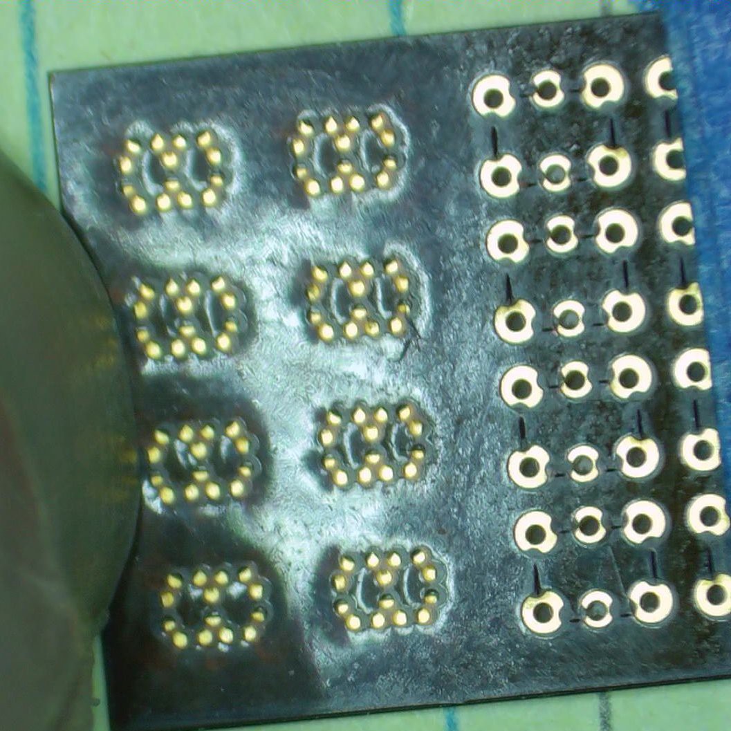
- This is supposed to be a "panel" of 8 modules in a 4×2 arrangement.
- The unplated through holes at the top of the photo? That's the paste stencil. Yes, this PCB acts as its own paste stencil!
- The top right module has had 0201 LEDs soldered to it already. The bottom right module had paste applied but no LEDs, which is why it looks shiny and flux-y.
- The LEDs are too crowded to line up straight, but they do all fit on the 0806 footprint!
- There should not be any soldermask or silkscreen on top of any copper sections; that is an error by the fab house that I chose to just live with.
I need to reiterate that the PCB is also a stencil. It's thicker than a "proper" polyimide stencil but IT WORKED. This is bonkers, my friends.
If Twitter's still working, you can see a video that I like a lot, here. It's where I reveal the scale of the solder job to the friend that had been watching me solder-streaming.
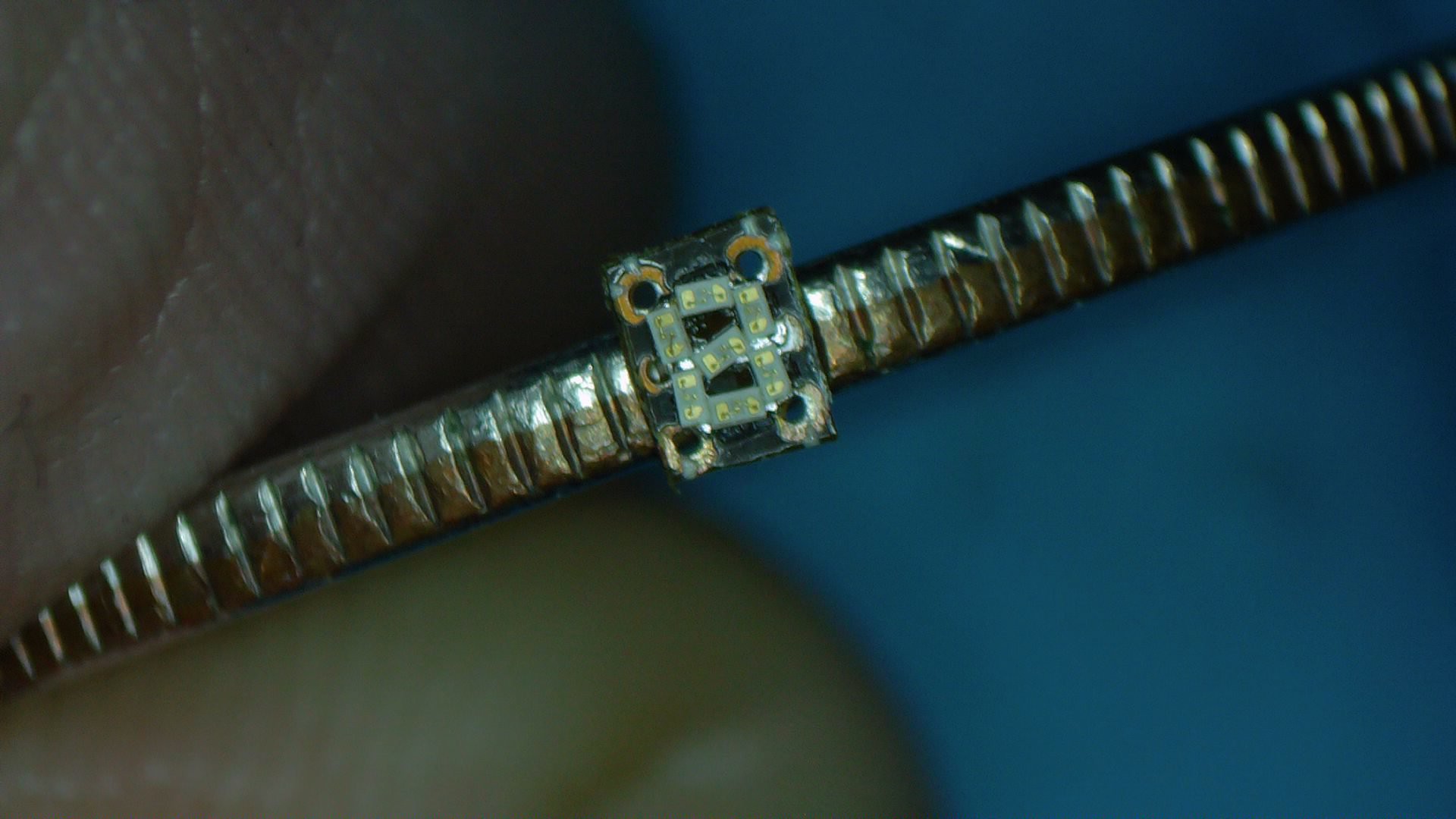
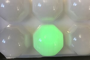
Here's one balanced on the edge of a U.S. quarter:
Experiment 1.5: A display board for the 6-pin 0806 modules
I didn't really do anything with these modules for a long time. They sat around for months and months, until Supercon rolled around. The good vibes there were what I finally needed to make these displays actually display something.
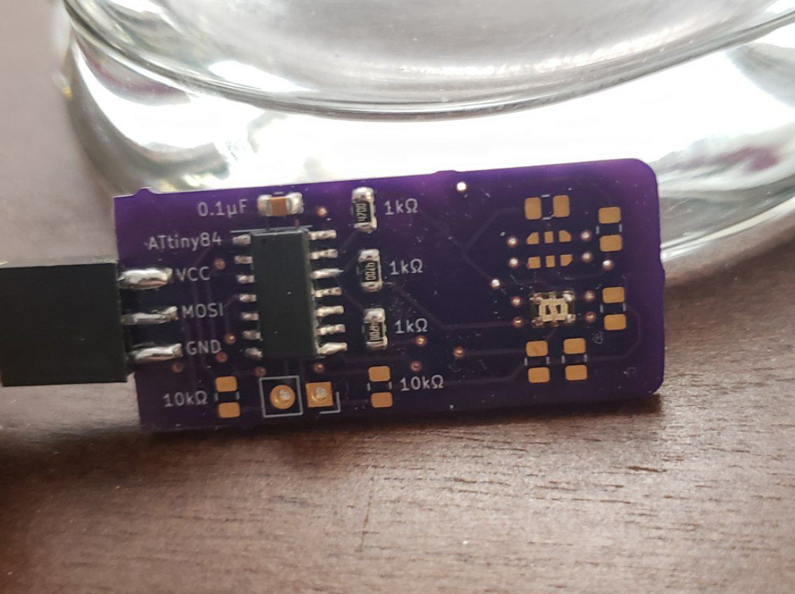
This is the project "6pin_7seg_0806_display_board" in the git repo. Notice one of the 0806 modules is soldered down on the right hand side! The microcontroller is an ATtiny84. I slapped together some bad, bad, bad code in order to get it into some sort of functional state display state. If Twitter's still around, here's a video of it in action at Supercon, cycling between displaying 0, 1, and 2.
Experiment 2: A 2-pin 7-segment display
If you look back at the original tweet, the 7-segment displays there had only two pins. What would it take to make that work? Well, there would need to be some kind of on-board microcontroller, instead of an external display driver. And the current-limiting resistors would have to be inside the module, too.
I have a little bit of experience with the 1.55×1.43 mm WLCSP-12 ATtiny20, which I could leverage here. And if I allow my I/Os to enter a high-impedance state, then I can drive all 7 segments with just microcontroller pins, brilliantly done by Rue Mohr, here.
I'm wondering if something like this could work:
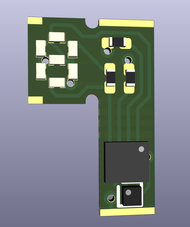
That picture is the opposite of self-explanatory, I know. Here's a lil bit of what's going on:
- This is, in theory, a flex PCB that folds up into a 1208 footprint with just two external pins.
- The external pins would be 0V and a voltage that can vary between, maybe, 3.3V and 5.0V
- The two ICs are a WLCSP ATtiny20 and a WLCSP 1.8V voltage regulator (because I have a few handy)
- The ATtiny20 has an ADC that can compare its working voltage with the 1.8V signal coming out of the regulator, and can use that to drive the displays. So perhaps the 3.30-3.39V range corresponds to a 0 on the display, 3.40-3.49V to a 1 on the display, etc.
- Alternately,...
 sjm4306
 Stephen Holdaway
 Leigh Oliver