 Mark VandeWettering
In one of my earlier project logs, I noted that the Arduino framework was a little bit annoying because it basically hides all the details having to do with interrupts from you, and that interrupts are powerful. If we look at the disassembled version of an Arduino sketch that does serial I/O, you will find that a lot of space is dedicated to the routines which handle the Serial object and the assorted Print helper functions.
For the 1Keyer, we want to be compact, minimal and efficient. Essentially all our input and output will consist of single characters, so all we really need is just some single I/O routines. But some degree of buffering is probably a good idea: I can easily type around 20WPM which is on the high side for most people's Morse code skills, and it isn't hard to bust out at 30WPM or 40WPM. If your keyed is set to 12 or even 5 WPM, you will easily get way ahead, and some buffering is a good idea.
Luckily, by virtue of the fact that we are using an Arduino module which has the ATmega328, we have about 2K of static RAM, of which we have used very little, and can dedicate it almost entirely for a keyboard type ahead buffer.
We could do (and still might do some) polled I/O...
First of all, we should note that it's not tremendously hard to do single character polled I/O without invoking the Serial object (and incurring all their cost). Mika Tuupola wrote a nice little tutorial that will explain most of the details, and some of the setup is the same even if we choose to with interrupts, so it's worth talking about.
The bare bones initialization code looks something (well, exactly like this, I swiped it from his tutorial):
#define F_CPU 16000000UL
#define BAUD 9600

#include <util/setbaud.h>

void uart_init(void) {
    UBRR0H = UBRRH_VALUE;
    UBRR0L = UBRRL_VALUE;

#if USE_2X
    UCSR0A |= _BV(U2X0);
#else
    UCSR0A &= ~(_BV(U2X0));
#endif

    UCSR0C = _BV(UCSZ01) | _BV(UCSZ00); /* 8-bit data */
    UCSR0B = _BV(RXEN0) | _BV(TXEN0);   /* Enable RX and TX */
}
Basically the first line defines the frequency at which the CPU operates. For a classic Arduino that operates at 5 volts, that is typically 16MHz. If you chose a 3.3V variant, they are commonly set at 8MHz. If you are using platform and specify a particular sort of Arduino, it knows what frequency you are after and provides this define for you.
Second is your choice of baud rate. 9600 is pretty typical. We could go faster, but it's kind of pointless too: 9600 baud is way faster than the keyer will ever be able to send Morse, so we might as well just loaf along at this slow rate.
You have to define both of these before you include <util/setbaud.h>. It's purpose is to calculate and define the UBRRH_VALUE and UBRRL_VALUE (the high and low bytes of the USART Baud Rate Register) to configure the onboard USART peripheral to generate the right timing. It also defines the USE_2X values, which I admit I don't really understand. But the final two lines configure the rest of the important stuff. The UCSR0C register mostly controls the size of the serial bits that you need: 8 is almost universally used everywhere, so just initialize it as shown. The UCSR0B register enables and disables functionality. Here, we want to be able to send and receive bytes, so we turn on the receiver enable RXEN0 and transmitter enable TXEN0 bits. And we are done!
Now, we can define two simple routines to get and put individual characters.
First, the receive:
char
uart_getchar(void)
{
    loop_until_bit_is_set(UCSR0A, RXC0); /* Wait until data exists. */
    return UDR0;
}
That seems pretty easy! It uses the loop_until_bit_is_set macro which is defined in one of the var-libc include files, and just waits until the RXC0 bit is set in the UCSR0A status register. The microprocessor will set that bit when a new character has been received and is ready to be read from the UDR0 register (USART Data Register 0). Send character is a little different. There are two ways that you can do it, I prefer this way:
void
uart_putchar(char c)
{
    loop_until_bit_is_set(UCSR0A, UDRE0); /* Wait until data register empty. */
    UDR0 = c;
}
This code loops until the USART Data Register Empty flag is set. This means that the UDR0 is available to store the next character to be sent. When this routine returns, it might be that the entire character has not been sent: it could (probably is) going to continue to be written out. But you don't have to wait until the character is totally sent before finding the next character to be queued up. I'll use this technique in my examples. We could also instead wait until the transmission is entirely complete before continuing. I can think of a few reasons to do that, by the time you understand this fully, you probably will too.But there are problems...
This code is a lot more compact than the code that you'd use from the Arduino framework (and much more barebones) and perhaps that is good enough. But it does share an issue with using the Arduino framework: it relies on polling. If you are in the middle of a call to delay() (say, while sending a dah from the keyed) and a character is received on the serial port) then you have to wait until the dah is completed before you can process it. But if we receive a second character, it's a real problem. The AVR has only a single character buffer, and we can't squeeze two (or more characters) into it.
The bulk of the code in the Arduino framework is actually designed to hide this complication from you by using interrupts. You can think of these as routines that are executed as an interruption of your main program. When the interrupt condition happens, then a routine (the interrupt handler, or in avr-libc, an ISR or Interrupt Service Routine) gets called. We can use this to implement a larger buffer which will prevent us from dropping characters. As long as every once in a while we drain the buffer of its contents, we'll be okay.
ECHO, written with interrupts
Rather than trying to immediately wedge this all into my 1Keyer project, I wrote a simple little test program that used some of these principles. It configures all of the USART parameters, and then uses the RXCIE (Receive Character Interrupt Enable) flag to say that we wish to receive interrupts whenever we receive a character. We then create an ISR which buffers up the character for later. For fun, we make sure that any letters are converted to uppercase. If the buffer is entirely full, then we turn off the interrupt, so we will effectively stop receiving characters. But if the buffer is large enough, we should be fine. The buffer is implemented as a fixed size array, with two indices that allow it to implement a circular buffer. When new characters are received, they are stored at the location specified by the buffer_tail, and the tail in incremented (with wrap around). To keep the indices small and compact, we are limiting them to 8 bits, so that means the maximum size of our buffer in they program will be 128 (if you tried to do 256, the code would have to be slightly more clever to discern empty from full).
If the buffer contains any characters, then we enable the USART Data Ready interrupt. It will generate an interrupt when you can place an output character in the output register. This does the reverse of the get routine. The character is read at the buffer_head, and then the head is incremented. If the buffer is empty, then the UDRIE0 interrupt is disabled.
Here is an example chunk of code:
#include <stdint.h>
#include <avr/io.h>
#include <avr/interrupt.h>
#include <avr/pgmspace.h>
#include <util/delay.h>

////////////////////////////////////////////////////////////////////////

#define RX_BUFFER_SIZE	(128)
#define RX_BUFFER_MASK	(RX_BUFFER_SIZE-1)

uint8_t buffer_head = 0 ;
uint8_t buffer_tail = 0 ;
uint8_t buffer_count = 0 ;
uint8_t buffer[RX_BUFFER_SIZE] ;

ISR(USART_RX_vect)
{
    uint8_t c = UDR0 ;
    if (c >= 'a' && c <= 'z')
	c = 'A' + c - 'a' ;
    buffer[buffer_tail++] = c ;
    buffer_tail &= RX_BUFFER_MASK ;
    UCSR0B |= _BV(UDRIE0) ;
    buffer_count ++ ;
    if (buffer_count == RX_BUFFER_SIZE)
	UCSR0B &= ~_BV(RXCIE0) ;
}

ISR(USART_UDRE_vect)
{
    UDR0 = buffer[buffer_head++] ;
    buffer_head &= RX_BUFFER_MASK ;
    buffer_count -- ;
    if (buffer_count == 0)
	UCSR0B &= ~_BV(UDRIE0) ;
}

////////////////////////////////////////////////////////////////////////

#define BAUD	9600

#include <util/setbaud.h>

void
uart_init()
{
    UBRR0H = UBRRH_VALUE;
    UBRR0L = UBRRL_VALUE;

#if USE_2X
    UCSR0A |= _BV(U2X0);
#else
    UCSR0A &= ~(_BV(U2X0));
#endif
    UCSR0B = _BV(RXEN0) | _BV(TXEN0) | _BV(RXCIE0) ;
    UCSR0C = _BV(UCSZ01) | _BV(UCSZ00) ;
}

void
uart_putchar(char c)
{
    loop_until_bit_is_set(UCSR0A, UDRE0); /* Wait until data register empty. */
    UDR0 = c;
}

int
main()
{
    uart_init() ;
    uart_putchar('1') ;
    uart_putchar('K') ;
    uart_putchar('\n') ;

    sei() ;

    for (;;) ;
}
If you look at main, you'll see that it initializes the uart, prints out three characters (using the polled uart_putchar routine that we mentioned before) and the calls sei() which is the Set Interrupt Enable() routine. Then, the program enters a loop which appears to do nothing. In fact, all the operation of this program happens in the ISR routines, which aren't explicitly called at all. If you connect to the Arduino after burning this firmware (I use platformio's serial ports monitor, which is convenient) you can test it out.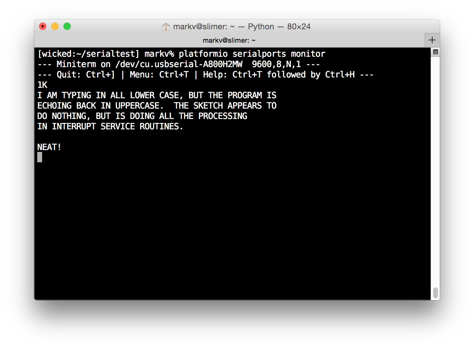
This program seems to have taught me what i need to know. I need to do a bit more thinking about exactly how I am going to use it in the final keyer project. I think that the main program will consist of my state switching code and generating all the dits and dashes. I'll augment the state machine to include a state which is entered when the buffer is empty, and whenever we are in the start state and a character is ready, we prefer to handle that rather than read from the paddles. When the character is complete, then we loop back to the start state.
Coming soon...
There is one bit of code left that I need to work out: how to generate the 700Hz audio sidetone. If we were using Arduino, that would be pretty simple, and just require the tone() call, but again, that would be a lot of code to include. Instead, we will initialize one of the on chip timer modules ourselves, and use it to generate the necessary 700Hz square wave on an output pin.
Once we have all that, the final program will be ready. We'll be pretty close in terms of size, and may require a bit of tweaking to get it under the 1K limit, but I am confident it's doable. I'll then do a couple of Youtube videos demonstrating its use, make sure the code is available from github and reasonably tidy, and provide hex files for download.
It's turning out to be a fun project. I hope you are enjoying it.
Discussions
Become a Hackaday.io Member
Create an account to leave a comment. Already have an account? Log In.