 psemportugal
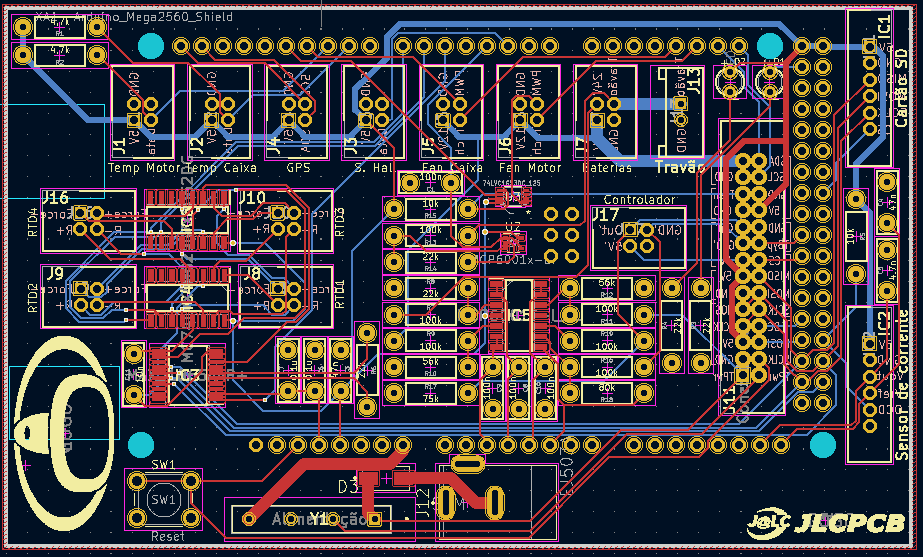
The dimension of the Shield is 109.576x65.151[mm], with 2.9 mm of thickness and two layers, slightly bigger than Arduino Mega(101.86x53.61 [mm]).
- Schematic
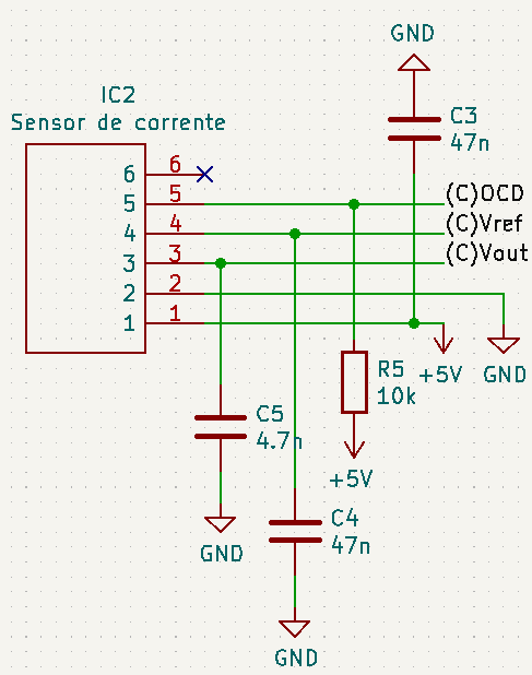
- Current Sensor
The Current Sensor is used to measure the current going through the cables that power the DC engine. All the additional logic used is an essential suggestion that can be found in the sensor data sheet.
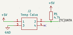
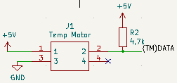
- Temperature Sensors
Our team uses two DHT ,temperature and humidity sensors, in order to prevent equipment damages.
The sensors are located in the Electronics Box and near the engine. The Electronics Box was created with the aim of protecting the Arduino and respective PCB from the environment elements, mainly water, so an additional Temperature sensor was necessary to obtain temperature and humidity data. The other sensor is located near the engine with the obvious purpose of measuring the engine temperature.
The only additional logic suggested in the data sheet was a pull-up resistor in the "Data" track, to prevent values fluctuation.
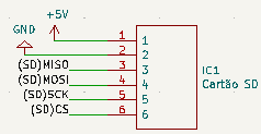
- SD Card
The SD card is an essential element in our electronic data acquisition,as it is used to save all the sensors data into csv files. The SD Card Reader uses SPI( Serial Peripheral Interface) to receive data from the microcontroller.
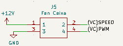
- Fans
Two PWM controlled fans are used in both cars, in order to cool, not only the engine, but also the electronic components inside the Electronics Box. Each fan has 4 pins, being one of them the PWM pin, that controls the duty cycle depending on the temperature of the environment where the fan is implemented. To allow the driver to put the fan at maximum speed in case of system failure, a bypass circuit was created where two wires are connected to a side box with a switch that determines whether the fan is being controlled by the Arduino or by the pilot. This circuit was only implemented in the motor fan circuit.
- TFT
In order to provide more data and, at the same time, have a better quality display, a TFT was implemented in the GP21. 7 new pins connected to the Arduino were added in a 28 pin connector so that the LCD could be used, being MOSI, CHIP SELECT, CLK,D/C and RESET 5 of the pins used to work with SPI Mode. Although the Touch Screen option is available, our team didn't find use to it.
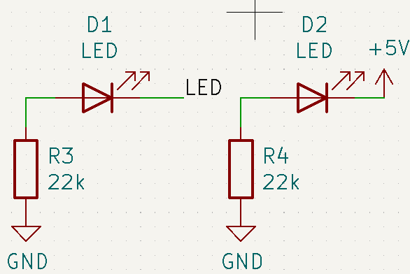
- Power and Code LEDs
Two LED were added with the purpose of checking if the board is on and receiving new code. One of the LED is always on and the other is connected to a digital pin that will be activated at 1 if the code is updated.
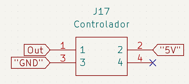
- Connection to the DC Motor Controller
The connection to the controller board consists in a 4 pin connector.
- Hall Sensor
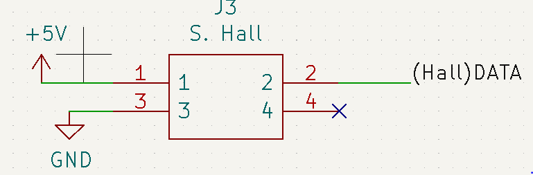
The Hall sensor is a type of sensor that detects the presence of a magnetic field using the Hall effect. Our team has the aim of using a sensor near the left rear car wheel that has a magnet attached to. It detects when the magnet passes through the sensor and by knowing the wheel perimeter and the time the magnet takes to do a full rotation, the car speed is calculated.
To connect the sensor to the board, a 4 pin connector is used, although just 3 of the pins are used and only one is a digital pin.
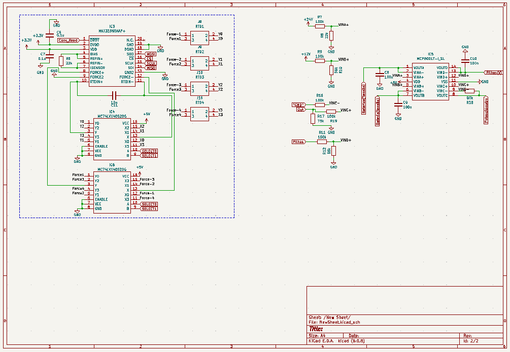
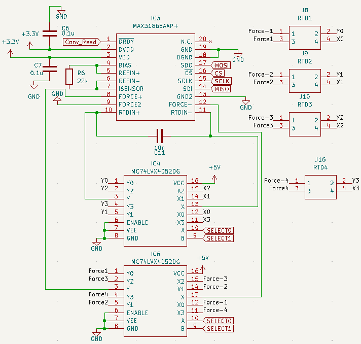
- RTDs
An RTD (Resistance Temperature Detector) is a sensor whose resistance changes as its temperature changes and the resistance vs temperature relationship is well known and is repeatable over time. As an RTD does not produce an output on it´s own, external electronic devices,in our case an Arduino, are used to measure the resistance of the sensor by passing a small electrical current through the sensor to generate a voltage.
In order to increase the accuracy of the measurements, a 4 wire RTD is used to eliminate the influence of lead wires.
All the additional logic is presented on the RTDs schematic and it's the product of research made by the team.
- Steering Wheel Encoder
A Steering Wheel Encoder was used so that the turning angle of the steering wheel could be studied. This encoder works with SPI and has 6 pins connected to the Arduino, being MISO, MOSI, CHIP SELECT and SCLK 4 of them. To connect the encoder to the micro controller a 28 pin connector was used.
- LCD
To keep the possibility of using the old LCD without having to build another board, 4 LCD pins were added to a 28 pin connector.
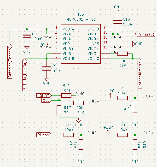
- Voltage Divider and Potentiometer
The voltage provided by the 12V batteries is too high for the Arduino, as the maximum voltage that can be supplied to the micro controller is 5V, so the use of an operational amplifier is necessary. To determine the potentiometer percentage, the operational amplifier is also used.
Operational Amplifier Data Sheet
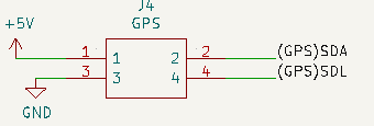
- GPS
A GPS was added to the cars in order to obtain position and velocity data. The data proved to be useful to other projects inside the team.
The connection to the Arduino is made with a 4 pin connector.
- Flaws and advantages
The RTDs presented before were not used in this year races, but the advantage of already having the circuit implemented on the board demonstrates the future proof characteristic of this PCB. To complement, the hall sensor was not used due to mechanical constraints, but the circuit is also on the board.
The GPS proved to be very useful as the hall sensor was not used and the only way to know the position, velocity and travelled distance was with the GPS.
The Electronics Box was also an excellent idea to protect the PCB and wires connected to it, providing also stability for the connections.
When it comes to flaws, unfortunately the sensors that work with the SPI protocol, SD Card Reader, Steering Wheel Encoder and TFT didn't work properly during the races, most likely because of the wires capacitance.