MQ2 is one of the commonly used gas sensors in MQ sensor series. It is a Metal Oxide Semiconductor (MOS) type Gas Sensor also known as Chemiresistors as the detection is based upon change of resistance of the sensing material when the Gas comes in contact with the material. Using a simple voltage divider network, concentrations of gas can be detected.
It can detect the gases and smoke anywhere from 200 to 10000ppm.
all the other basic sensor modules, this MQ-2 Gas and smoke sensor module has four pins, two of which are for VCC and Gnd and the other two can simultaneously output analog and digital data. To power the circuit we are using the 5V pin of the arduino because the operating voltage range of this module is 5V with ±0.1% tolerance. As you can see in the image above the module has two onboard LEDs. The power LED turns on when power is applied to the board and the Dout LED turns on when the trigger value set by the potentiometer is reached. This board also has a comparator OP-Amp onboard that is responsible for converting the incoming analog signal from the gas sensor to a digital signal. We also have a sensitivity adjustment Trim-pot, with that we can adjust the sensitivity of the device. Finally we have some resistor capacitors for decoupling and filtering.
his mesh structure also provides resistance against dust and other suspended particulars and it only lets in the gaseous elements from the atmosphere. If we decap the sensor we can see the sensor is made out of two major elements. First one is the heating element which is made out of nichrome wire and other is the sensing element that is made out of a platinum wire with a coating of tin dioxide. Now we don't want you to cut and damage you sensor, so we have done that for you, the below image shows the mesh decapped from the actual sensor

When you are working with this type of gas sensor there is a pre heat time or stabilization time that is required for this device to work properly. And if you check on the datasheet of the device you can see it says it requires a pre-heat time of 24 hours. So, Does this mean that it needs to be powered on for 24 hours constantly before usage?
The obvious answer to this question is a big fat NO. It simply means that to obtain typical performance data that is shown in the datasheet, you need to run it constantly for 24 hours. And it's been measured after 24h in their lab. So, if you want to be within specification you must observe that 24h preheating time. Given the small size of the sensor, thermal equilibrium will be almost surely reached within 30 min. And it would probably take just a few minutes to be within a few percent of the data provided by the datasheet.

The 24 hours preheat time will only matter if you want a very accurate measure of gas concentration, and you also have to have a good calibration of your sensor, as well as some means to compensate for other environmental factors like temperature, humidity, etc.
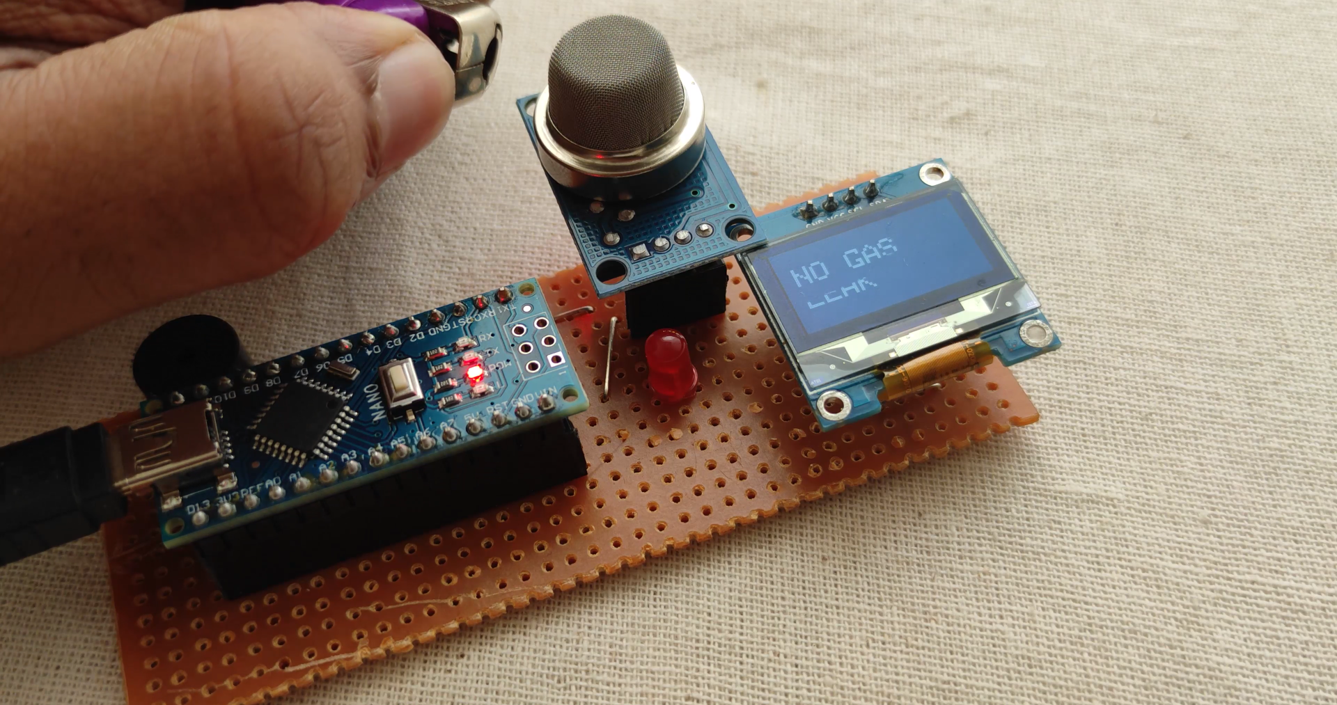
The MQ-2 Gas sensor can be used for both Detecting the gas and also for Measuring Butane and Hydrogen Gas level in PPM. Do note that detecting the gas and measuring its concentration in PPM is completely two different things. This article mainly focuses on detecting the gas level and increase in its concentration. If you want to exactly calculate the gas level in PPM the procedure is different, however we will also slightly touch on it.
As you can see in the above gif we have a can containing LPG gas when the gas is sprayed the gas concentration in the surrounding increases and when we spray that the second and the third time the concentration of gas increases again. When the gas concentration increases the output voltage from the sensor also increases you can observe this in the multimeter. And when it reaches a certain threshold (which can be set by the potentiometer) the green LED on the module lights up. You can observe this in the backside
Let's take an example of the LPG curve which is the pink one and see how we can calculate the slope of the curve, for that lets start with the X and Y coordinates that is 200 and 1.8 approximately So, the first data point from the logarithmic scale is (log200, log2) which is (2.3,0.0.255). The point for the ending curve is X1 and Y1 that is 1000 and 0.18 that becomes (log1000, log0.18) thus it becomes (4, -0.744). To get the slope of the curve, the formula is
=(Y1- Y) / (X1-X)= (-0.744 - 0.255) / (4 - 2.3)=-0.587
n the schematic, we have a LM393 op-amp which is a low-power low offset voltage op-amp that can be powered from a +5V supply. But powering the circuit with 3.3V is not an option because the minimum operating voltage of this MQ-2 sensor is 5V. The main job of this op-amp is to convert the incoming analog signal to digital signal. Other than that we also have an onboard 10K potentiometer that is used to adjust the sensitivity of the MQ-2 Gas Sensor module or the triggering voltage of the module.Other than that we have two LEDs. The first one is a power LED and the other one is the trigger LED. The power LED turns on when power is applied to the board and the trigger LED turns on when a certain set threshold is reached. Finally we have two decoupling capacitors that are used to reduce noise in the board.