0%
0%
Ethernet circuit discussion forum. Come on!!!!!
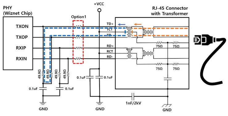
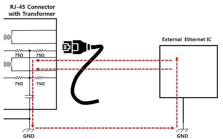
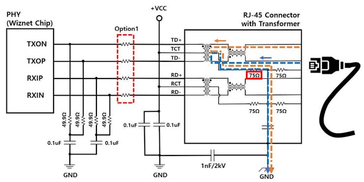
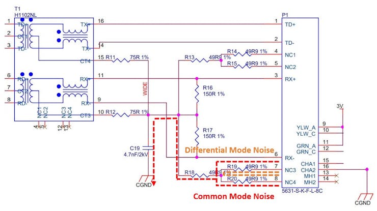
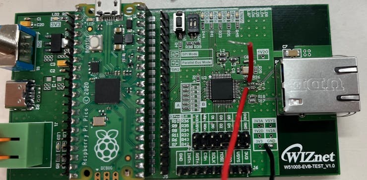
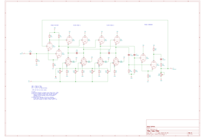
I experimented with the Ethernet MDI circuit.
 Alan
AlanBecome a Hackaday.io member
Already have an account? Log in.
Just one more thing
To make the experience fit your profile, pick a username and tell us what interests you.
Pick an awesome username
hackaday.io/
Your profile's URL: hackaday.io/username. Max 25 alphanumeric characters.
Pick a few interests
Projects that share your interests
People that share your interests


 256byteram
 sky-guided
 kevarek
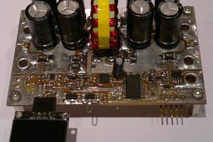
An Ethernet circuit typically refers to a physical or logical connection established using Ethernet technology for the transmission of data. Ethernet is a widely used networking protocol that defines the way data packets are placed on the network