 Manuel Tosone
Overview
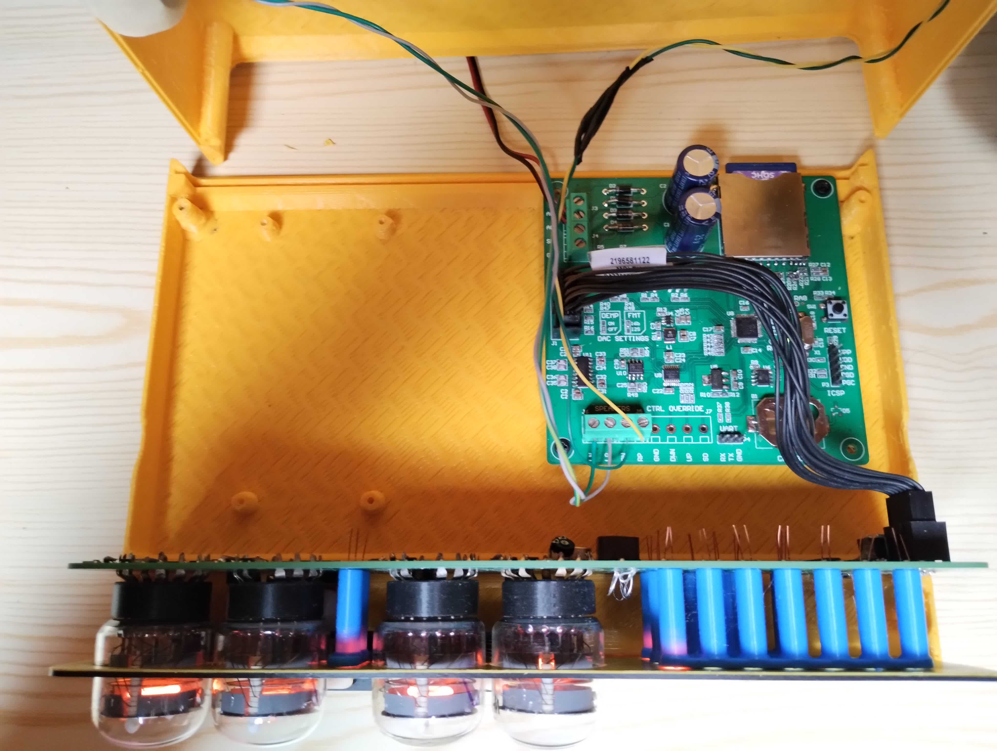
The clock is made of two PCBs housed inside a 3D-printed enclosure.
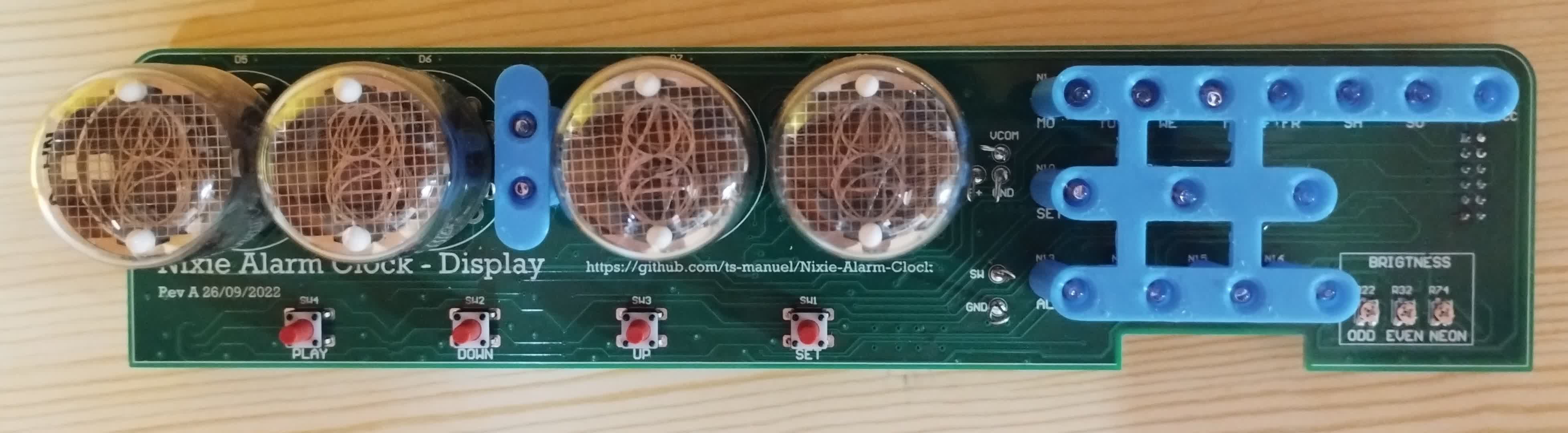
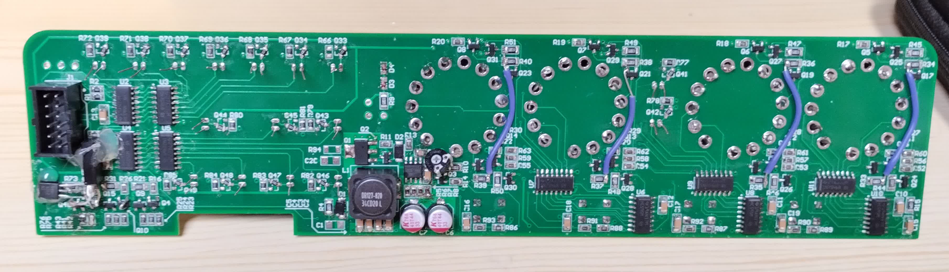
The display PCB has all the circuitry required for driving the nixie tubes and the neon lamps. This includes a 180 V boost converter to dive the anodes, shift registers to interface with the baseboard, and high-voltage transistors.
The base PCB is where the magic happens. There is an SD card where the songs are stored, a PIC24 microcontroller that drives the display and reads data from the SD to drive a 16-bit DAC through I2S, and a stereo class D 2x3 W audio amplifier.
All the PCBs were ordered on PCBWay, they offer a great low-cost service for prototyping, and their boards are always of high quality.
Display Board
The schematic can be found here.
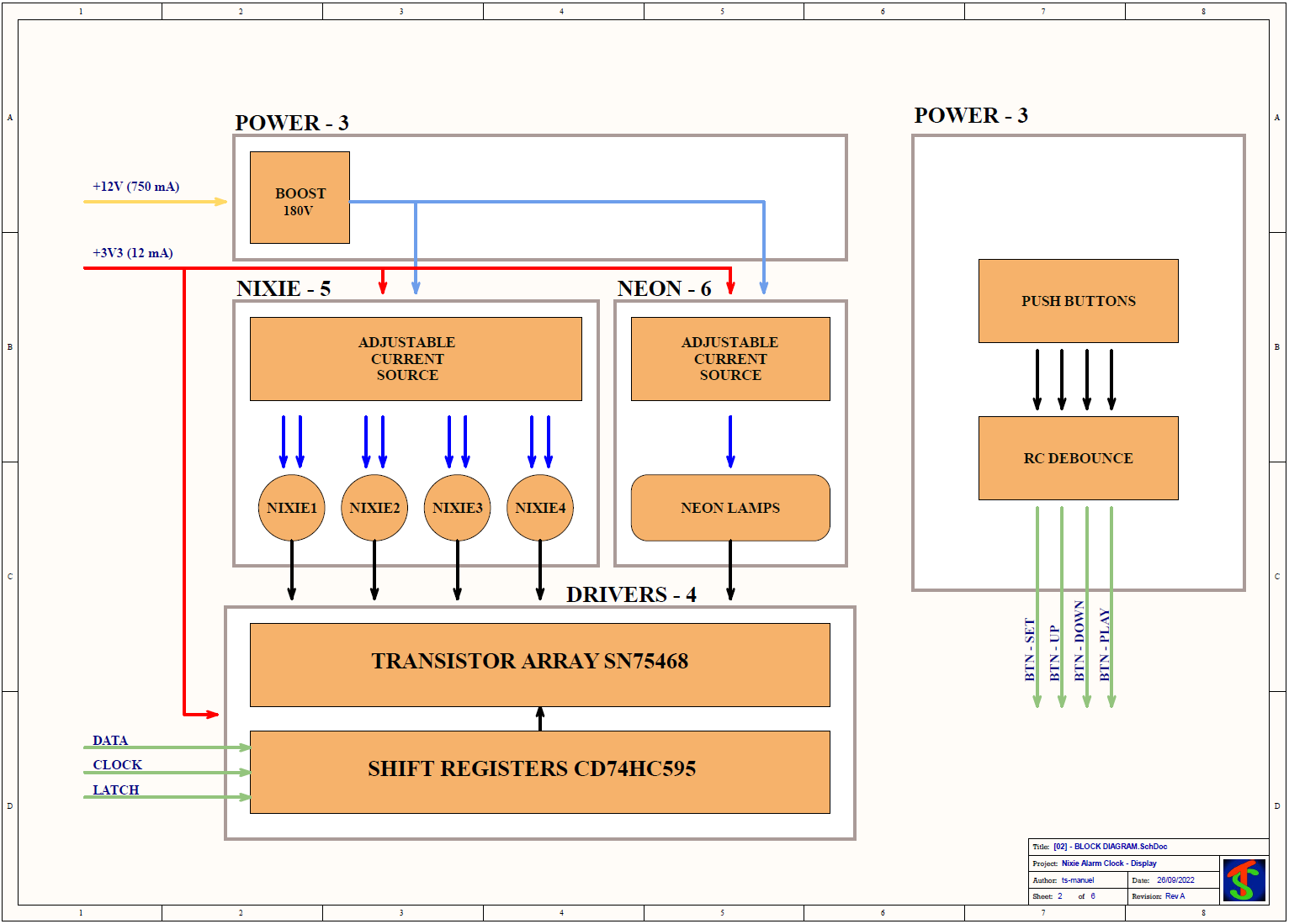
The base board supplies 3.3 V for the logic and 12 V for the boost converter. The boost converter generates the 180 V required to light the nixies. With this project, I wanted to try something different, instead of using the classical approach of a current-limiting resistor for each anode, there is a current source made with a BJT (more on that later). The cathodes are driven by SN75468 transistor arrays, they are the same as the classical ULN2003 but can handle a higher collector voltage, 100 V instead of 50 V. The base board interfaces with the display through shift registers that directly drive the transistor arrays.
Boost Converter
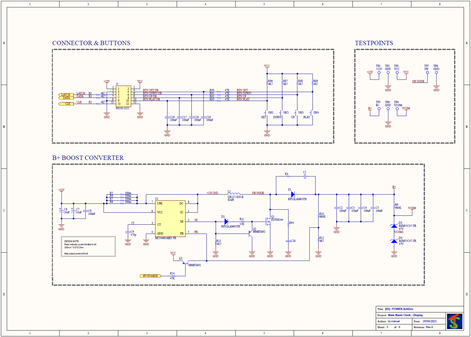
The boost converter is built around the MC34063A switching controller. The parallel combination of R5 R6 R7 R8 limits the peak inductor current to 4A giving a maximum output current of 40 mA at 180V. Q2 is there to quickly discharge the MOSFET gate capacitance, fast turnoff is critical for achieving high efficiency. The two series zeners generate the required grid voltage to drive the nixies in biquinary mode.
There is a mistake in the schematic that took me a while to figure out. When I first powered the circuit the output voltage was 180 V as it should but the current consumption was 1 A even with no load. The controller was operating at the full duty cycle and the MOSFET was dissipating a lot of power. The problem was that I somehow choose the wrong MOSFET, FDT86244 has a maximum Vds voltage of 150 V and it just happened to break down at 180 V, giving a false impression that the converter was regulating.
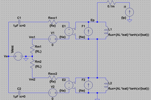
Nixie Current Source
Why don't you just use a resistor?
Well, current sources have two advantages. You can change the brightness on all the nixies by turning a potentiometer. Originally I wanted to change the brightness of odd and even digits separately but after playing with the display for a while it seems not necessary. I use IN4 nixies and by how they are constructed the odd digits are at the back of the tube, increasing the brightness on those will make them easier to see. The second advantage is that when the tubes get older the operating voltage increases, driving them with a current source will, at least in theory, make them have the same light output even at the end of their life.
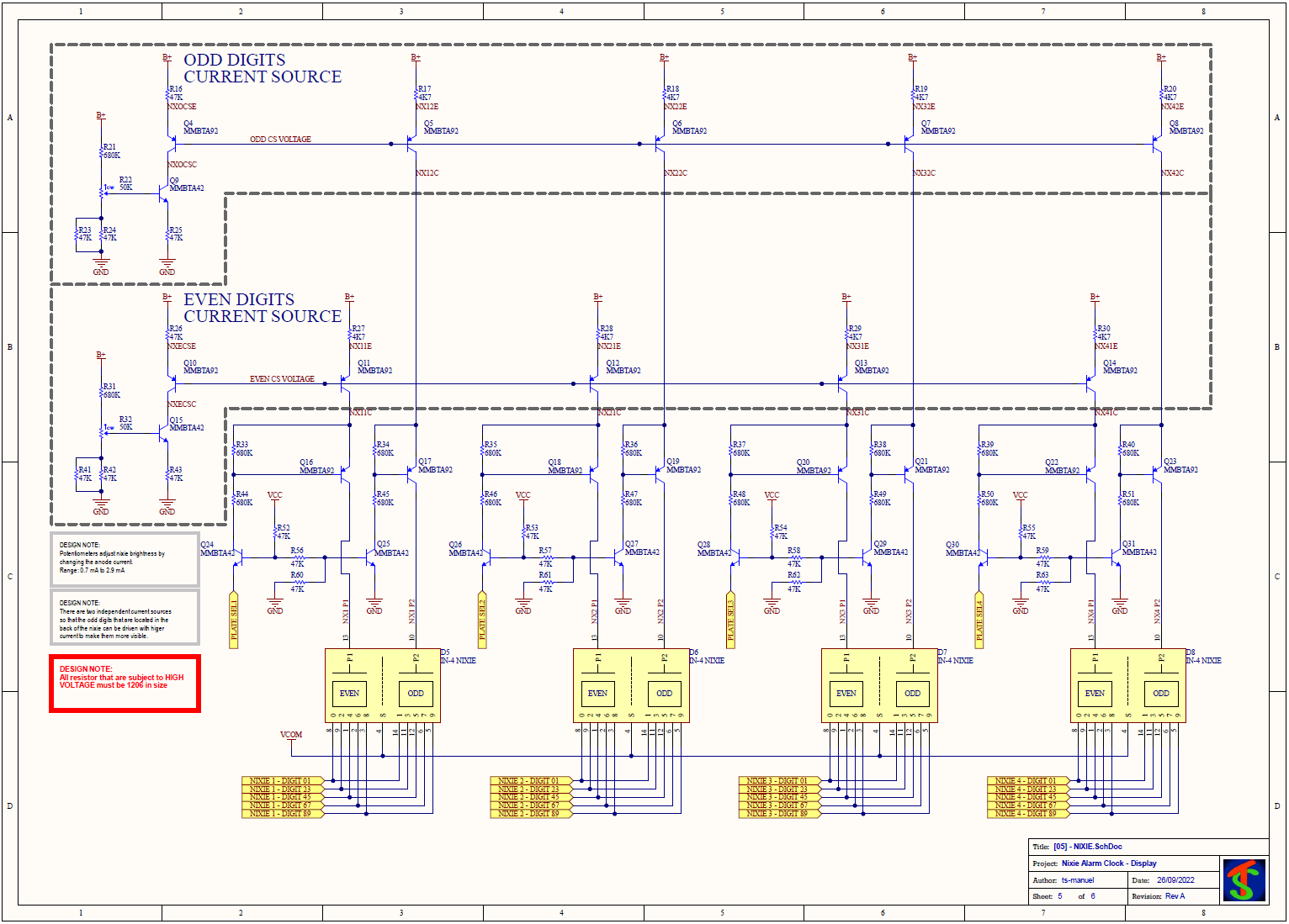
I had to make some modifications to the circuit to make it work. When designing the circuit I did not consider what happens when one of the collectors of the paralleled current sources is left floating, this happens when a nixie or neon lamp is turned off. With the collector floating the current flowing into the emitter has come out of the base, the increase in current offsets the bias point on all the other transistors. The effect is that when one current source is left floating the current on all the others becomes so small that all the nixies turn off.
Base Board
The Schematic can be found here.
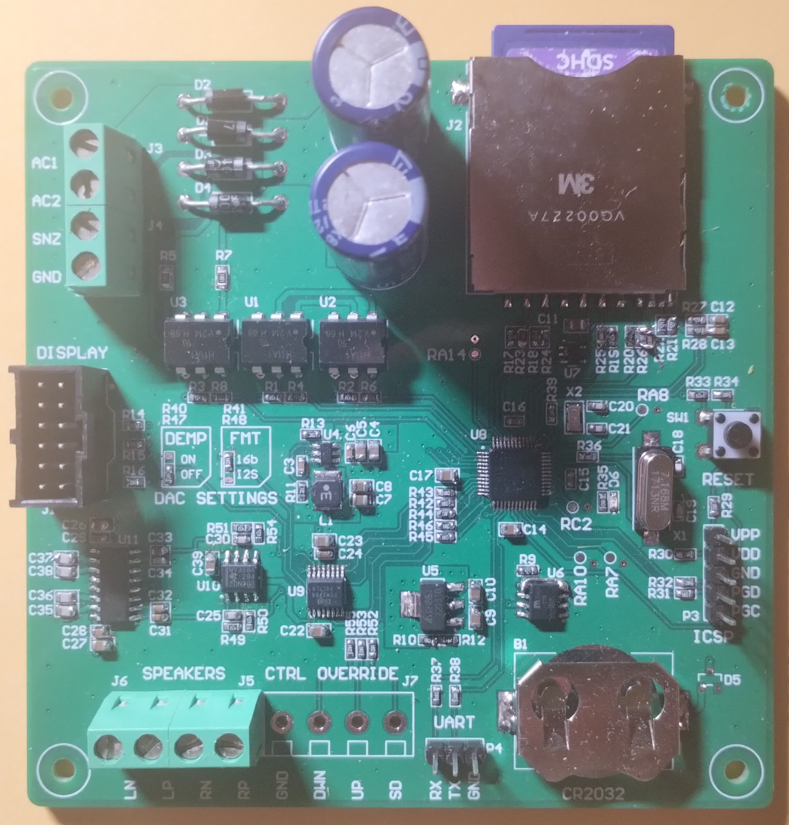
The base board is powered by 12 VAC from the mains transformer. The rectified 12 V is sent unregulated to the display to power the boost converter. The analog section is supplied with 5 V by a buck converter. The digital section operates at 3.3 V derived from the 5 V with an LDO. There is a power switch that isolates the...
Read more »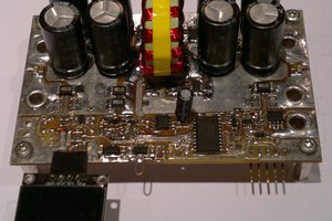
 jbb
jbb
 Andy
Andy
 Yann Guidon / YGDES