Close
0%
0%

ESP32 Drone

I wanted to make a low cost drone with all the bells and whistles, so people working with a small budget can get into the drone game. ~$50

Public Chat
Similar projects worth following
This project is using the ESP-WROOM-32 as the main flight controller which will utilize it's WIFI feature for communication and control, GPIO to run DC motors, SPI and I2C to run the camera which is a ArduCAM mini 2mp plus and also the 3 axis Gyro scope MPU6050.

Parts list:
1 x ESP-WROOM-32 DEVKIT 1
1 x ArduCAM mini 2mp plus
1 x MPU6050
4 x Crazepony 6x15mm Motor
4 x P-Channel MOSFET SMD Transistor AO3401A

For the controller, I'm going to be using software to control the drone. To do this it will be using rawdrawandroid which will allow an android phone/table to connect to the ESP and control the drone. This will allow for control from other platforms as well and not just limit it to just a phone or tablet.

This project will not be a high end drone. There will be limits as to the quality for the video feed and distance at which this thing will work. Really this thing is just a hack for things that are not supposed to be used in this way. Hence why it will be cheaper.

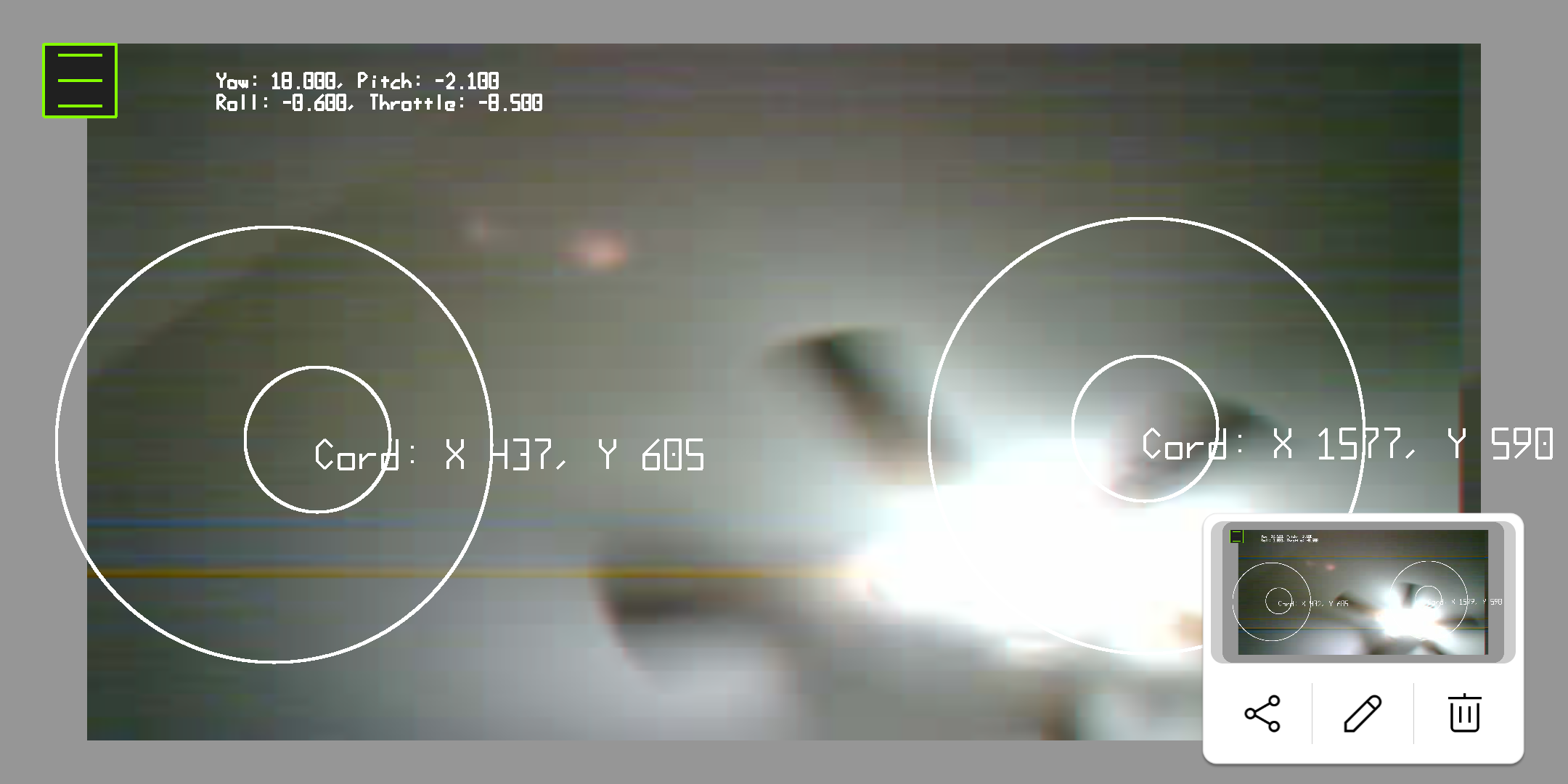
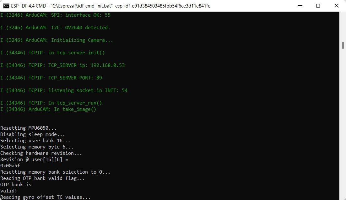
Video for most drone's is done VIA analog NTSC/PAL interface. This project is using a digital SPI/I2C interfaced camera with a max FPS currently of about 10-15. The base camera module is a OV2640 that is attached to a board with a controller IC and buffer with about 4 or 8mbs of ram for buffering.

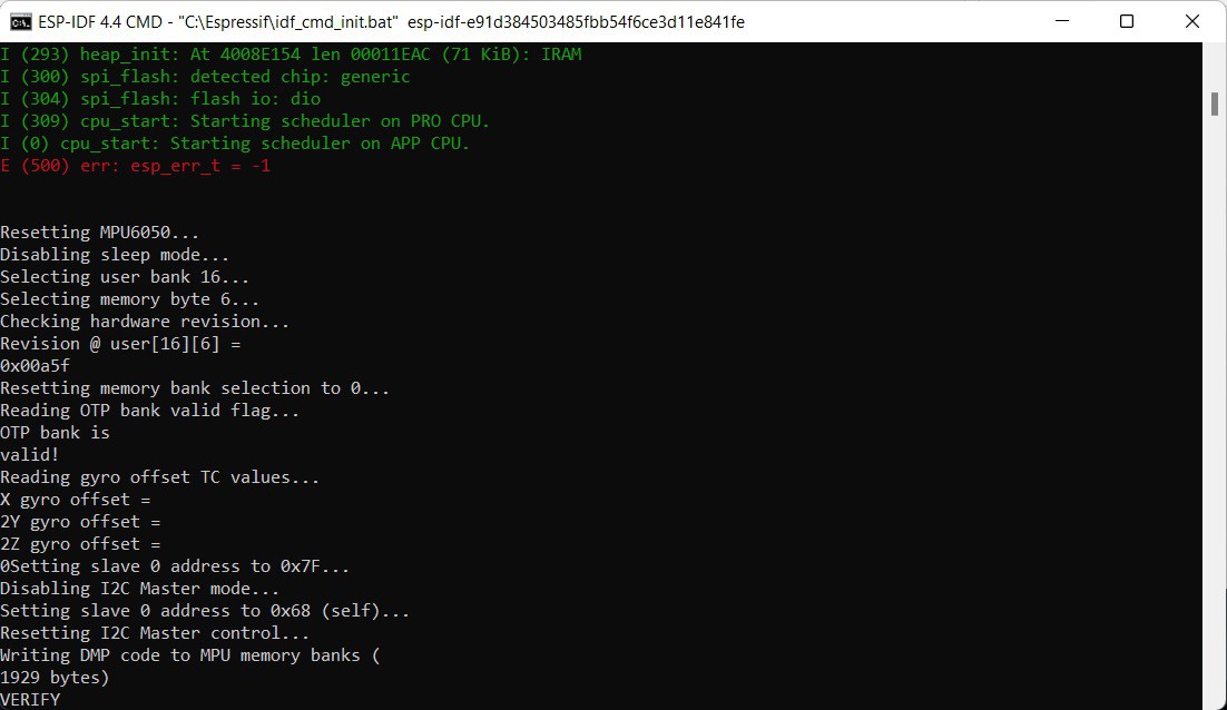
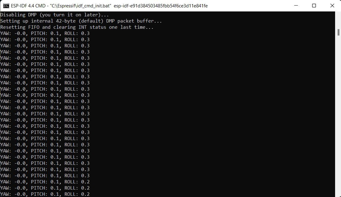
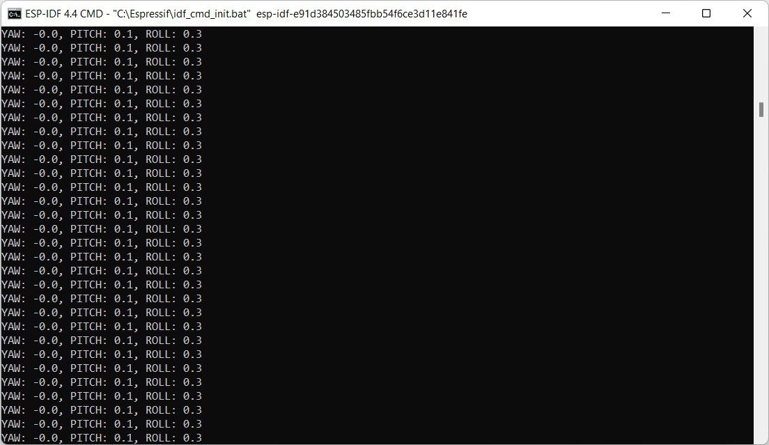
The ESP board wasn't exactly designed for this usage, handling the PID for control and stabilization from the gyro. Along with WIFI communication and video streaming from the camera will be a challenge in it's self. there will definitely need to be a good bit of optimization and maybe some inlining to get this thing to do all that it needs to do.

The point of this project is to get people a foot in the door to play with drones, electronics and code at a low cost. Something they can possibly build off of as they go.

At one point I was one of those kids, I was that person. Working with limited resources and limited funds helps to breed inventiveness. How can we get something to work as we want it to, that isn't exactly designed to do what we want?

40mm_X_4_mod.STEP

Cad file for propeller

step - 778.08 kB - 12/09/2022 at 16:18

Download

Drone Frame.STEP

Cad file for Frame

step - 4.06 MB - 12/09/2022 at 16:17

Download

  • 1 × ESP-WROOM-32 DEVKIT 1
  • 1 × ArduCAM mini 2mp plus
  • 1 × MPU6050
  • 4 × Crazepony 6x15mm Motor
  • 4 × P-Channel MOSFET SMD Transistor AO3401A

View all 9 components

  • Time flies when your having fun

    Jon VB03/04/2023 at 19:48 0 comments

    Been pretty busy with redesigning the drones frame to fit the Dev kit board of the ESP32 along with the MPU and Camera. This redesign helped to reduce weight over all for the drone. The weight went from about 70-80 grams down to about 50 grams. Also added some wiring routes for the motors to try and help keep the wiring cleaned up. 

    The Camera module can now be slid into place easily and removed just the same with no screws. the MPU and MCU are attached to the frame via mounting posts. No, screws should be used here just a bit of hot glue. The MCU also helps to keep the frame ridge to help reduce the frame weight. No, glue on post will make the structure flimsy.

    There were some problems trying to get the propellers to print with out errors. I completely redesigned the props to make contact with the print bed along with giving them more surface area at middle and extending a bit more to the tip of the blade.

    I started to use a 60C lipo battery and noticed the ESP32 was freezing up when throttle was added to the motors. Took me a bit to figure out the mistake that I had made. with the old battery that was being used the voltage was closer to 3.3V, the newer battery was a good bit higher at 4.2V the pull up resister was placing about 3.8V to the GPIO of the ESP32. After some looking I noticed this and needed to place a TTL logic level N-Channel MOSFET to allow the circuit to function correctly. 

    Along the way, I also noted that the custom blit_image() function that I was using need to be pulled from the rawdraw project and placed into the projects GUI's *.c and *.h files respectively. This was something that barryjoehawkes had caught. I thank him for that, since I didn't even notice it when I was uploading the project to GitHub.

  • Code... Code everywhere... Code updates

    Jon VB01/03/2023 at 20:53 0 comments

    Okay, this is going to be a smaller log. Holidays and everything has made life pretty busy so short and sweet for now.

    The camera, communication and control has been put together for the ESP32 along with some code clean up. Got ride of some commented out code related to allot of earlier debugging, fixed some logic in the code layout primarily in the TCP end of things. Got rid of allot of over nesting and unnecessary logic bits. After everything has been put together I'm getting about 13 FPS from the ESP. This can probably be improved upon, but that will have to come later. All this has been uploaded to ESP_Drone on GitHub for those interested in having a look.

    Along with my code clean up for the ESP32 I did about the same thing for the android side of things. Cleaned up allot of over nesting and unnecessary code. Along with the clean up another thing that I wanted to do was scale up the image since it's only at 320 x 240. This was done using a global added to rawdraws CNFGFunctions.c the globals used are scale_h and scale_w used respectively in CNFGBlitTex().

    float scale_h = 0, scale_w = 0;
    
    void CNFGBlitTex( unsigned int tex, int x, int y, int w, int h )
    {
        if( w == 0 || h == 0 ) return;
    
        CNFGFlushRender();
    
        CNFGglUseProgram( gRDBlitProg );
        CNFGglUniform4f( gRDBlitProgUX,
            1.f/gRDLastResizeW, -1.f/gRDLastResizeH,
            -0.5f+x/(float)gRDLastResizeW, 0.5f-y/(float)gRDLastResizeH );
        CNFGglUniform1i( gRDBlitProgUT, 0 );
    
        glBindTexture(GL_TEXTURE_2D, tex);
    
        /*  two triangles
                                  
            (0,255)----------(255,255) 
              |                  |     
              |                  |     
              |                  |
            (0,0)------------(255,0)
        */
    
        volatile uint8_t a = 255, b = 255;
    
        // Added scaling to the rectangle that the image will be drawn on
        const float verts[] = {
            0,0, (float)w * scale_w,0, (float)w * scale_w,(float)h * scale_h,
            0,0, (float)w * scale_w,(float)h * scale_h, 0,(float)h * scale_h };
            
        const uint8_t tex_verts[] = {
            0,0,   a,0,  a,b,
            0,0,   a,b,  0,b };
    
        CNFGglVertexAttribPointer(0, 2, GL_FLOAT, GL_FALSE, 0, verts);
        CNFGglVertexAttribPointer(1, 2, GL_UNSIGNED_BYTE, GL_TRUE, 0, tex_verts);
    
        glDrawArrays( GL_TRIANGLES, 0, 6);
    }

     Along with the above code modification, moved around the order of the drawing for the top hat control so it is not drawn over by the displayed image. 

    Results:

    Sorry for the pic of my ceiling fan lol. It's just how I got the camera wired up right now. There is also a good bit of noise in the images that I will need to clean up, most of this is due to how it's currently wired up for the time being. Got some work to do on the image and getting the controls fully flushed out. For now I'm content with that it's giving me, till after I get some running tests with the full unit. The code for the android side of things can be found here ESPStream. I will have the updated code pushed to GitHub later tonight.

    Now I'll be working on getting the drone wired up and ready for some testing. I do plan on building a gimbal rig to check for proper flight instead of yolo'ing it and hoping it works. That would only spell disaster and possibly breaking the unit and parts them selves. I plan on having a gimbal designed and printed up in the next week. I'll post the wiring up process and the first proto unit here in the next few days.

  • Cobbling more together, MPU, PWM and PID

    Jon VB12/20/2022 at 20:05 0 comments

    So, after a good bit of time, I was able to put together 3 of the main parts of this project. This should really get this thing going. It took a good bit of searching, recoding and trial/error got it working. So I'm pleased with that.

    I did a push to GitHub for this bit of code. This is mainly for motor control and stabilization. The code can be found here. If anyone wants to have a look at it. Suggestions and help are more then welcome.

    PWM

    Okay, so jumping into what has been done. First, started off with getting the PWM working correctly. This was accomplished using LEDC from ESP-IDF. This can all be found in the component directory of your ESP-IDF installation under C:\Espressif\frameworks\esp-idf-v4.4.2\components\driver\include\driver\ledc.h dependent on your install of course. At first I tried to find an exact replacement that Arduino was using for the build environment then decided to just cut out the middle man and go to the source it's self. There is a good example of how this works, which I went off of here. Props to the author for keeping it simple and to the point. Gave me a good spot to jump off of to start searching/digging from there. 

    At this point I had to flush out the hardware design for the DC motors. Since the MOSFETs I would be using are P-Channel Enhancement mode MOSFETs both the gate and source had to be tied to Vcc and the drain tied to ground.

    The gate was tied to Vcc via a pull up resistor to keep the MOSFET in the off position. What I did here was just create an electronic switch. Were the logic from the GPIO pin is set to Pulse Width Modulation will toggle this switch to give the desired power to drive the DC motor. For my usage, the logic of the GPIO had to be inverted to compensate for this reverse logic setup of the MOSFET.

    If you'd like to learn more about basic electronics check out this site and read up on some of the basics. There are allot of good sites to check out, just pick one that feels good for you and charlie mike. I used a bunch of different sites while I was attending school so no site is a one size fits all, that I know of yet.

    PID and MPU

    After all that was said and done, got a solid test out of my setup, I went on to the next piece. Tying the MPU, PID and PWM together. I did find a software PID library that was used in the Arduino code I had used already in the Arduino build environment, it just needed a little bit of a modification to get it to work with the ESP-IDF build environment. The Original code can be found here if you want to play around with it a bit, the modified version is included in the component directory of my Git repo for this project.

    PID can be a pretty big subject and used for more than the application that this project is using it for. So if you want to dive deeper into this area you can check this out and read up on the subject. As I'm just going to touch on a few things here to show how I'm interacting with the PID controller.

    As a basic jest of it. I'm getting the yaw, pitch and roll from the MPU converting that number to an angle then feeding that number into the PID control via an input. But first the PID controller needs to settle for a little bit. the setup I got going it doesn't have any PID tunning, if left for brief period of time the controller will level out giving a better result. the following code achieves this to an extent.

    // PID Cal while throttle is at 0
    if (target_speed[0] == 0)
    {
        ESP_LOGI("PID", "CALIBRATING...");
        ypr_cal[0] = ypr[0] * 180 / M_PI;
        ypr_cal[1] = ypr[1] * 180 / M_PI;
        ypr_cal[2] = ypr[2] * 180 / M_PI;
    }

     I know this is a sloppy way of doing but it'll work for now. what really matters is the input variable being set here, from the data we got from the MPU.

    // getting yaw, pitch and roll from MPU
    mpu.dmpGetYawPitchRoll(ypr, &q, &gravity);
    printf("YAW: %3.1f, ", ypr[0] * 180 / M_PI);
    printf("PITCH: %3.1f, ", ypr[1] * 180 / M_PI);
    printf("ROLL: %3.1f\n", ypr[2] * 180 / M_PI);
    ...
    Read more »

  • MPU magic and starting to pull things together.

    Jon VB12/11/2022 at 20:27 0 comments

    Alright, so I got to looking at the Arduino build code for the motors with PWM and... of course the PID and MPU6050 were all coded in together. What I ended up doing was working on the gyro first.

    What I had to do was find a library that would work with the MPU6050 and the ESP-IDF build environment. Luckily, there was such a thing, that's here and I wasn't going to have to start from scratch. Also, it has an awesome little test example which I could use to to do a function check really quick.

    I did run in to an issue with the example, nothing ever works perfectly on the first try. If it does that generally tends to worry me as there might be an issue further on down the line. The issue was with their sdkconfig file. They seemed to have some different boot image options enabled for a different board that wasn't going to jive with the current board I am using for this build. So, being the lazy person I am, I just copied a version of the sdkconfig that I had from a different project over to it and that seemed to fix the boot image issue that I was having.

    Great Success, yes! got some good initialization messages along with some good telemetry data.

    MPU6050 being initialized:

    MPU6050 telemetry data:

    Good stuff, I proceeded to see if there would be any issues with the gyro working with the camera. Since they both use the I2C interface. Which of course there was... Dug a little bit and with some critical thinking realized both the camera and the gyro both are using different libraries to use the I2C interface. Small brain move on my part I then remembered that the ESP32 has more than one I2C port, I2C_NUM_0 and I2C_NUM_1 so... instead of rewriting or scrambling to find something thing that would work with both of the devices. I opted to just use both of the I2C interface ports and save some time.

    Doing this required having to change the SDA and SCL pin numbers for the MPU6050. SCL got assigned to 16 and SDA got assigned to 17. Also, since the library being used for the gyro is in C++ I had to add a header to the example and a little #ifdef __CPLUSPLUS magic so my C could see the functions in the object files that were compiled in C++.

    Related header file:

    #ifndef EXAMPLE_H
    #define EXAMPLE_H
    
    #define PIN_SDA 17
    #define PIN_CLK 16
    
    #ifdef __cplusplus
    extern "C" {
    #endif
    
        extern void task_initI2C(void*);
        extern void task_display(void*);
        
    #ifdef __cplusplus
    }
    #endif
    
    #endif

    With that out of the way, it appeared to work correctly. Got a good initialization from the camera and also the same from the gyro along with telemetry data. 

    Camera initialization and beginning of Gyro initialization:

    Some Telemetry data:

    with this I just wanted to function test that both the camera and gyro would work together with out any issues which appears to be the case for now.

    For the rest of the day I will probably be working on getting the code for the PID and PWM for the motors working, if there's enough time in the day I will see if I can get the gyro, PID and PWM all working together on the same thread. We'll see if I can get that far.

  • Trying to get things in order

    Jon VB12/09/2022 at 16:39 0 comments

    I have a list of things I need to do in order to "complete" the project by Jan 3 dead line or get it as close as possible by that time.

    1. Get code unified and ported over to Espressif's ESP-IDF. I have most of the code for GPIO PWM for the motors and Gyro already done but under Arduino's build environment for the ESP32.
    2. Figure out how I'm going to get the PID control for the Drone that works in conjunction with the gyro into ESP-IDF. I have not even looked into this yet, as I've been down some other rabbit holes recently with this project.
    3. Get hardware setup for testing in step's to work with new ported code. Going to have to get bread board setup for testing motor's and gyro again...
    4. As I figure out more that's needed I will add to this list. 

    Was working on a menu interface for the Android portion of this build to make it easier to connect with the ESP, For now at least, thinking I'm going to put this on hold and leave as hard coded. This just has to do with the IP address and port number for the TCP side of things.

     For today, I just want to try and get the GPIO PWM code written up for ESP-IDF and maybe test with the motor's if I got time to do that.

View all 5 project logs

Enjoy this project?

Share

Discussions

andac colak wrote 12/15/2023 at 18:14 point

Hello, I need to create an image processing project called line-following drone. can i do it this way

  Are you sure? yes | no

FranciscoCM wrote 08/04/2023 at 14:10 point

Well done Jon. Are you still working in this project? I´m working on similar challenge. I would like to join this project if it is still active.

  Are you sure? yes | no

ap-tech wrote 06/13/2023 at 00:18 point

This thing is just awesome love the simplicity, Are you doing any machine vision stuff with the camera?

  Are you sure? yes | no

Simon wrote 04/25/2023 at 12:33 point

Cool project - what is the overall weight of your drone?

  Are you sure? yes | no

Jon VB wrote 06/12/2023 at 17:27 point

With a PCB it's under ~60g, sorry for the delay.

  Are you sure? yes | no

Marc wrote 04/14/2023 at 00:11 point

Hello, Can I use this project for a final project for my course? and could I ask you if I have any questions? It would be super nice and you are a genius, greetings

  Are you sure? yes | no

Marc wrote 04/14/2023 at 00:14 point

I have one, do you know how I could make it remotely controlled? with an app, blueetoh or wi-fi? 

  Are you sure? yes | no

Jon VB wrote 06/12/2023 at 17:23 point

Please take a look at the ESP Drone code. As most of that is there. Sorry for the delay, been inactive due to a cross country move and dealing with some mental health issues. Anymore issues feel free to ask.

  Are you sure? yes | no

Jon VB wrote 06/12/2023 at 17:26 point

Heck yeah! Go right ahead. Flattered. I will be working on another larger version once I got time. You be more then welcome to jump on board if you're feeling froggy.

  Are you sure? yes | no

[deleted]

[this comment has been deleted]

Jon VB wrote 04/04/2023 at 14:16 point

thank you! sorry for the response delay. XD

  Are you sure? yes | no

barryjoehawkes wrote 03/05/2023 at 11:20 point

Well done Jon. Thanks for new model, software mods and new photos. Question, where do you intend to put the Mosfets? I see you have no connections to D25, 26, 32 and 33 so the model is not complete.

  Are you sure? yes | no

Jon VB wrote 03/05/2023 at 17:23 point

You are correct, that is when I noticed I made a goof. Thought it was a software issue or some other type of hardware issue with power boot up, but that wasn't the case. I had also tried some different sets of pins as well. You got a keen eye, didn't notice I kept them where they where, going to move them back to where they had been in the schematic so I'll update that and post it here. Guess I had been a bit hasty to post an update, it had been a good bit since I had done so. Didn't want to leave people hanging with no news for so long. 

As for the FETs I was just direct soldering them with the through hole resistors I have to make a package that get's some shrink tubing. So far I've just been securing them under the frame. I'm waiting on the n-channel Mosfets to move forward at this point. I'm not planning on making a PCB for this yet till everything is in working order.

Also, check your private messages for this site got a question for you.

  Are you sure? yes | no

barryjoehawkes wrote 01/28/2023 at 12:19 point

Jon VB, ESP32 side of things now OK i.e. output as per your blog

Android side not so. I have 'pushed' Rawdrawandroid and cnfgtest.apk runs OK on the tablet. I have done the same with ESPStream and 'pushed' ESPStream.apk to the tablet but it opens and shuts immediately. I obtained the following error

"bhawkes@iMac ESPStream % adb logcat | grep UnsatisfiedLinkError

01-27 15:33:08.930 5677 5677 E AndroidRuntime: java.lang.UnsatisfiedLinkError: Unable to load n ative library "/data/app/~~xs5yLF-p01RLbqBzGUBNg==/org .yourorg. ESPStream-P2IsVnRrDSJUldJdRbLRcQ= =/lib/arm64/libESPStream.so": dlopen failed: cannot locate symbol "scale_h" referenced by "/data/ app/~~rs5yLF-pOURLbqBzGIBNg==/org.yourorg.ESPStream-P2IsVnRrDSJIldJdRbLRcQ==/lib/arm64/libESPStr eam. so'"

 Any advice, or should I just be patient and wait for your further blogs.

  Are you sure? yes | no

Jon VB wrote 01/29/2023 at 22:23 point

Sorry for the delay man, that error is my fault I didn't realize that I linked rawdraw directly into my project on github. I have a custom blitimage() function that I had to write in order to display images from the cam. I just now realized this upon seeing your comment. So when I pushed my files to github apparently those didn't go through because they would change rawdraw. So, what I need to do is pull those functions that I had to tweak out and put them some place else other than directly in rawdraw. I'll probably end up putting them in "gui.c" I'll get on that as soon as I'm done with the frame redesign. 

Been pretty busy with the frame design, making sure everything fits nice, good clearances for the props and duct, and also making sure that when the motors heat up they don't become "too" lose.

I'll PM you after I get those functions pulled out and put in a good place then pushed to github. Sorry if this slowed ya up a bit. 

  Are you sure? yes | no

barryjoehawkes wrote 01/12/2023 at 18:46 point

Jon VB, I'm following your project with interest. Have installed EPS-IDF (ver 5.0) on my iMac M1 running Ventura 13.1.

'Hello_World' example runs OK showing things are working but ESPStream/EPS32 cloned from git.hub today does not compile.

I attach snippets from the 'pdf_py_stdout_output_xxxxxx" below to illustrate some of the failures. Can you suggest where I should seek a solution? I would not like to drop out at this beginning stage.

828/849] Building C object esp-idf/wifi_provisioning/CMakeFiles/__idf_wifi_provisioning.dir/src/scheme_softap.c.obj
[829/849] Building C object esp-idf/main/CMakeFiles/__idf_main.dir/main.c.obj
/Users/bhawkes/esp/ESPStream/ESP32/main/main.c: In function 'app_main':
/Users/bhawkes/esp/ESPStream/ESP32/main/main.c:73:33: warning: passing argument 1 of 'xTaskCreatePinnedToCore' from incompatible pointer type [-Wincompatible-pointer-types]
   73 |         xTaskCreatePinnedToCore(take_image, "take_image", 8192, (void *)&thread_args, tskIDLE_PRIORITY+3, NULL, 1);
      |                                 ^~~~~~~~~~
      |                                 |
      |                                 void (*)(void)
In file included from /Users/bhawkes/esp/esp-idf/components/freertos/FreeRTOS-Kernel/include/freertos/timers.h:44,
                 from /Users/bhawkes/esp/esp-idf/components/freertos/FreeRTOS-Kernel/include/freertos/event_groups.h:42,
                 from /Users/bhawkes/esp/ESPStream/ESP32/main/network_wifi.h:5,
                 from /Users/bhawkes/esp/ESPStream/ESP32/main/main.c:22:
/Users/bhawkes/esp/esp-idf/components/freertos/FreeRTOS-Kernel/include/freertos/task.h:345:56: note: expected 'TaskFunction_t' {aka 'void (*)(void *)'} but argument is of type 'void (*)(void)'
  345 |     BaseType_t xTaskCreatePinnedToCore( TaskFunction_t pvTaskCode,
      |                                         ~~~~~~~~~~~~~~~^~~~~~~~~~
[830/849] Building CXX object esp-idf/arducam_esp/CMakeFiles/__idf_arducam_esp.dir/ArduCAM_esp.cpp.obj
FAILED: esp-idf/arducam_esp/CMakeFiles/__idf_arducam_esp.dir/ArduCAM_esp.cpp.obj 
/U

……….

switch-conversion -DconfigENABLE_FREERTOS_DEBUG_OCDAWARE=1 -std=gnu++20 -fno-exceptions -fno-rtti -D_GNU_SOURCE -DIDF_VER=\"v5.0\" -DESP_PLATFORM -D_POSIX_READER_WRITER_LOCKS -MD -MT esp-idf/arducam_esp/CMakeFiles/__idf_arducam_esp.dir/ArduCAM_esp.cpp.obj -MF esp-idf/arducam_esp/CMakeFiles/__idf_arducam_esp.dir/ArduCAM_esp.cpp.obj.d -o esp-idf/arducam_esp/CMakeFiles/__idf_arducam_esp.dir/ArduCAM_esp.cpp.obj -c /Users/bhawkes/esp/ESPStream/ESP32/components/arducam_esp/ArduCAM_esp.cpp
In file included from /Users/bhawkes/esp/ESPStream/ESP32/components/arducam_esp/ArduCAM_esp.cpp:1:
/Users/bhawkes/esp/ESPStream/ESP32/components/arducam_esp/ArduCAM_esp.h:5:10: fatal error: driver/gpio.h: No such file or directory
    5 | #include "driver/gpio.h"
      |          ^~~~~~~~~~~~~~~
compilation terminated.
[831/849] Linking C static library esp-idf/fatfs/libfatfs.a
[832/849] Linking C static library esp-idf/mqtt/libmqtt.a

…………………….

ESPStream/ESP32/components/arducam_esp/ArduCAM_esp_ov2640.cpp
In file included from /Users/bhawkes/esp/ESPStream/ESP32/components/arducam_esp/ArduCAM_esp_ov2640.h:4,
                 from /Users/bhawkes/esp/ESPStream/ESP32/components/arducam_esp/ArduCAM_esp_ov2640.cpp:1:
/Users/bhawkes/esp/ESPStream/ESP32/components/arducam_esp/ArduCAM_esp.h:5:10: fatal error: driver/gpio.h: No such file or directory
    5 | #include "driver/gpio.h"
      |          ^~~~~~~~~~~~~~~
compilation terminated.
[834/849] Building C object esp-idf/arducam_esp/CMakeFiles/__idf_arducam_esp.dir/interface_spi.c.obj
FAILED: esp-idf/arducam_esp/CMakeFiles/__idf_arducam_esp.dir/interface_spi.c.obj 
/Users/bhawkes/.espressif/tools/xtensa-esp32-elf/esp-2022r1-11.2.0/xtensa-esp32-elf/bin/xtensa-esp32-elf-gcc  -I/Users/bhawkes/esp/ESPStream/ESP32/build/config -I/

……….

-D_POSIX_READER_WRITER_LOCKS -MD -MT esp-idf/arducam_esp/CMakeFiles/__idf_arducam_esp.dir/interface_spi.c.obj -MF esp-idf/arducam_esp/CMakeFiles/__idf_arducam_esp.dir/interface_spi.c.obj.d -o esp-idf/arducam_esp/CMakeFiles/__idf_arducam_esp.dir/interface_spi.c.obj -c /Users/bhawkes/esp/ESPStream/ESP32/components/arducam_esp/interface_spi.c
In file included from /Users/bhawkes/esp/ESPStream/ESP32/components/arducam_esp/interface_spi.c:1:
/Users/bhawkes/esp/ESPStream/ESP32/components/arducam_esp/interface_spi.h:1:10: fatal error: driver/spi_master.h: No such file or directory
    1 | #include "driver/spi_master.h"
      |          ^~~~~~~~~~~~~~~~~~~~~
compilation terminated.
[835/849] Building C object esp-idf/main/CMakeFiles/__idf_main.dir/network_wifi.c.obj
FAILED: esp-idf/mai

…………..

/Users/bhawkes/esp/ESPStream/ESP32/main/tcp_server.c:54:62: error: request for member 'ip' in something not a structure or union
   54 |         esp_ip4addr_ntoa((const struct esp_ip4_addr *)&ipInfo.ip, sc->ip, 16);
      |                                                              ^
/Users/bhawkes/esp/ESPStream/ESP32/main/tcp_server.c: In function 'tcp_server_write':
/Users/bhawkes/esp/ESPStream/ESP32/main/tcp_server.c:201:35: warning: unused variable 'vsps' [-Wunused-variable]
  201 |         video_stream_packet_state vsps;
      |                                   ^~~~
cc1: some warnings being treated as errors
[838/849] Building C object esp-idf/wifi_provisioning/CMakeFiles/__idf_wifi_provisioning.dir/src/manager.c.obj
[839/849] Building C object esp-idf/spiffs/CMakeFiles/__idf_spiffs.dir/spiffs/src/spiffs_nucleus.c.obj
ninja: build stopped: subcommand failed.

  Are you sure? yes | no

Jon VB wrote 01/12/2023 at 23:49 point

Okay, for the ESP it's self, the code you should be using is this https://github.com/SelfTide/ESP_Drone

The code you were compiling was just meant as a test for rawdrawandroid. Sorry I haven't written up a how-to just yet. still working on it.

Now going off that, and what I can see in your error log. You are going to have to move the components directory from the project into your frameworks/esp-idf-v( what_ever_version_your_using)/components directory for ESP-IDF. So if you cd to /Users/bhawkes/esp/ESPStream/ESP32/ and use `mv components /where/your/ESP-IDF/components/directory/is/` that should solve the components issue. As for the warnings those are non-issues right now for me.

The Error with `struct esp_ip4_addr` that might be a mac issue. Honestly, you could just comment these three lines of code and that should fix the error

```

esp_ip4addr_ntoa((const struct esp_ip4_addr *)&ipInfo.ip, sc->ip, 16);

ESP_LOGI(TAG, "TCP_SERVER ip: %s\n", sc->ip);

ESP_LOGI(TAG, "TCP_SERVER PORT: %d\n", sc->port);

```

Those where just really there to let me see if thing were working correctly. They aren't really needed.

If you got anymore questions feel free to message me and I'll get back to you as soon as I can :)

  Are you sure? yes | no

dhruv wadhwa wrote 12/25/2022 at 07:01 point

I guess you used the dmp example of the mpu6050 library. it uses interrupts but u haven't used the int pin in the schematics. could you please explain a bit

  Are you sure? yes | no

Jon VB wrote 12/25/2022 at 17:02 point

Here is the code I went off of: 

https://github.com/jrowberg/i2cdevlib/tree/master/ESP32_ESP-IDF

It's not really needed, or I felt it wasn't, unless I felt a need to poll the int pin and read data exactly when the pin is raised. I didn't want to create another thread and have to deal with more thread communications.  With the example code for ESP-IDF `mpu.getIntStatus();` is used to check for interrupt status. This function is accessing this information via I2C and not the INT.

```

uint8_t MPU6050::getIntStatus() {
I2Cdev::readByte(devAddr, MPU6050_RA_INT_STATUS, buffer);
return buffer[0];

}

```

So no need for int pin really, unless we got some code that is taking to much processing time, this will cause issues. In this case it would be best to use an ISR - Interrupt Service Request.

You could use an ISR and "poll" the GPIO pin that is associated with the int pin for the MPU. Here's an example to go about doing that if you were so inclined to do so. 

https://github.com/espressif/esp-idf/blob/master/examples/peripherals/gpio/generic_gpio/main/gpio_example_main.c

  Are you sure? yes | no

dhruv wadhwa wrote 12/25/2022 at 17:34 point

how are u computing yaw pitch and roll? is it from the raw acc and gyro data?

  Are you sure? yes | no

Jon VB wrote 12/25/2022 at 22:51 point

Yes, then feed the raw data from the MPU's FIFO stream to the corresponding library's functions to turn it into something more readable. the only thing that needed to be done after the dmp functions was to convert it to an actual angle that we can interpret.

  Are you sure? yes | no

dhruv wadhwa wrote 01/29/2023 at 20:06 point

i do not quite get it... to clear the fifo u need interrupts. i does work without connecting the int pin but that is very unreliable coz it causes mpu to glitch and freeze sometimes.

  Are you sure? yes | no

Jon VB wrote 01/29/2023 at 22:09 point

okay, please read https://invensense.wpenginepowered.com/wp-content/uploads/2020/06/PS-MPU-6500A-01-v1.3.pdf particularly 4.15 the first paragraph, last sentence. it states "The interrupt status can be read from the Interrupt Status register." 

Also, please look at figure 6 and 7 at 4.9.2 of the data sheet. The INT pin is not connected, the only thing is a note stating the INT pin should be connected to bring the AP out of suspend mode if it has been put into suspend mode, that is the host uC is hibernating or the user has put the uC into a suspended state etc.

As for clearing the FIFO, I've seen nothing in the data sheets stating that the INT pin has to be connected to clear the FIFO. If you have documentation stating that it does I'd like to look at it.

  Are you sure? yes | no

Benjamin wrote 12/24/2022 at 15:15 point

Hey, we also use an ESP32 with the espressif IDE as an autopilot. The ESP32 is an awesome uC.

Details and code are here:

https://hackaday.io/project/188136-kites-for-future-flying-wind-turbine

We were inspired by Joop Brokking's youtube videos.

  Are you sure? yes | no

Jon VB wrote 12/24/2022 at 16:59 point

Wow! that is so cool! I remember people having idea's about these a while back. thank you for the heads up! I will definitely be looking into this :D and yes this little uC can do so much it's ridiculous.

  Are you sure? yes | no

Peabody1929 wrote 12/12/2022 at 02:07 point

Just a thought on motor control:  Four DC motors of the same type may not rotate at the same speed when driven by the same waveform. The idea is to get the same downward thrust from each motor/prop. To get the quadcopter drone to hover, you may need a compensation factor for each motor/prop combination to make their output identical.  

  Are you sure? yes | no

Jon VB wrote 12/12/2022 at 03:04 point

That's the idea with the gyro and PID control. unless there is a direct input from the control system it should auto balance the pwm accordingly. that's if the gyro is calibrated correctly or as close as possible. :) thanks for the input and a good reminder on that subject. been a couple months since I touched that part of it. went down a rabbit hole with rawdraw and the little camera I had been playing with. thanks man! :D

  Are you sure? yes | no

Jon VB wrote 12/12/2022 at 03:54 point

Since you mentioned it, I'll go over a bit of this on my next log entry.  Because that is what I'm currently working on while porting my code over from Arduino's build environment. Maybe add some graphics for context.

  Are you sure? yes | no

jamesmartinjr wrote 12/09/2022 at 02:31 point

Looks sick! definitely will make when i get the time to!

  Are you sure? yes | no

Jon VB wrote 12/09/2022 at 02:53 point

Thanks man! still a work in progress... gotta get all the code wrapped up together. everything is in pieces right now, motor control, cam, and gyro. just got to cobble everything together.

  Are you sure? yes | no

Similar Projects

Does this project spark your interest?

Become a member to follow this project and never miss any updates