 mit41301
Intended use:
RDA Microelectronics make RDA7088N is a simple FM Tuner with stereo output. As per datasheet we need not to have a host to program this FM Tuner IC. Just connecting 5 tactile switchs we can make a standalone FM radio receiver. The audio output from the IC is capable of driving pair of 32 ohms speaker. The tuner supports 76-108MHz band. We can generate RCLK using a standard 32.768kHz crystal and have inbuilt AGC feature.
The pinout of RDA7088 IC is as below
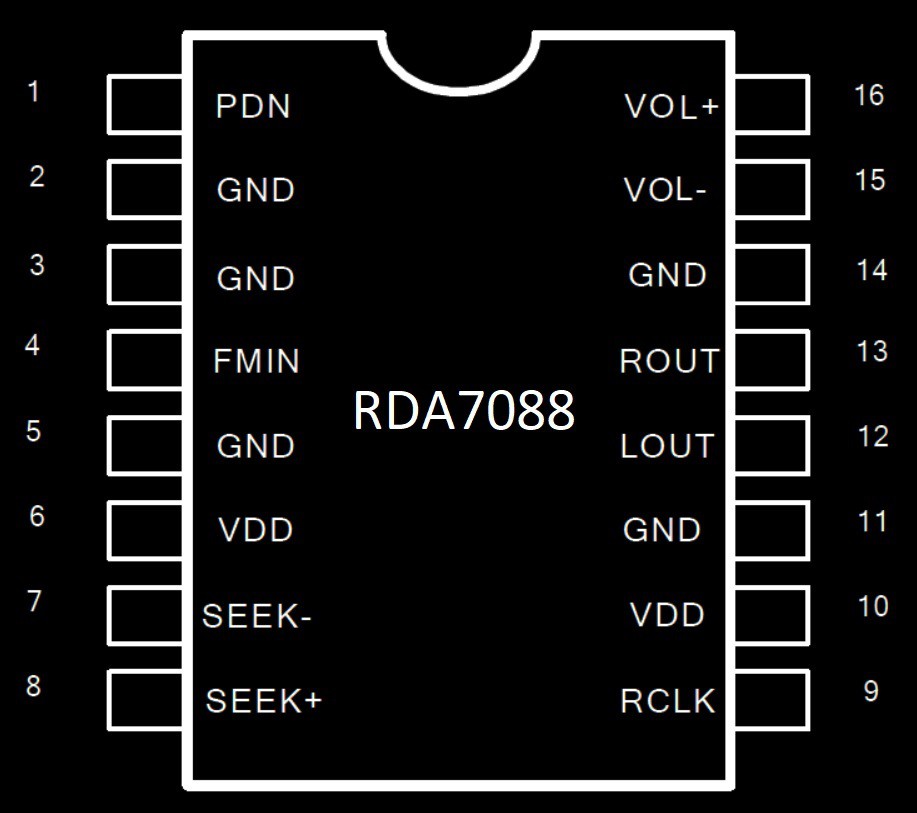
We can control power ON/OFF (PDN-1), Channel seek+(#8) /seek-(#7) and Volume using VOL+(#16)/VOL-(#15). The tuner's internal operation is controlled by a tiny FSM(Finite State Machine) inside the IC.
Basic application circuit is as below
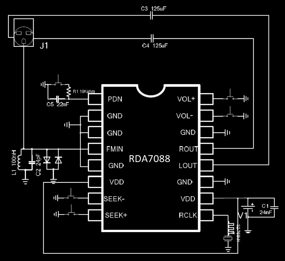
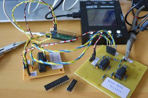
Tested few RDA7088N ICs with breadboard along with DIP to SOP16 adapter. Everything works as per datasheet. FM tuner IC directly drives the 32 ohms headphone directly.
HACKED VERSION:
As per the RDA7088N pinout there are two VDD pins (6 and 10). Pin#10 is the actual VDD and Pin#6 is nothing to do with VDD. If you connect the RDA7088 IC pin#6 to VDD then the FSM is active and you can control the IC with tactile switches connected to pin# 1,7,8,15&16.
If you connect the RDA7088 IC pin#6 to GND then the IC will function as a I2C controlled stereo receiver with RDS and I2S features!!!
I²C INTERFACE!
When we connect the RDA7088 pin 6 to GND, then the FSM is disabled and I2C bus will be active. Now we can control the RDA7088 using standard I2C bus along with RDA family programming specifications.
Tested with PIC10F200 in SOT23-6 and DIP-8. It worked well with I2C bus. Since PIC10F200 is having only 4 I/O pins , added IR infrared remote control so that we can add many functions in future by just using only one input pin. Since GP3 is input only pin it is decided to use that pin for IR remote control input. After successful implementation on PIC10F200 with I2C protocol with IR remote control, little curious to explore the I2S feature of the RDA7088 IC. Looking through RDA FM tuner family datasheets and after doing some simple tests using PIC10F200, able to implement the I2S output from RDA7088 with IR remote control.
There are many Arduino sktches available for FM Tuner using RDA5807M, TEA5767, Si4703 or AR1010 etc., for easy testing through I2C bus.
The pinout of RDA family FM tuner available in SOP16 is as below picture.
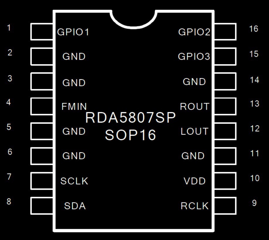
Pin 7(SCLK) and pin 8(SDA) are used for I2C communication. There are three GPIO available for user.
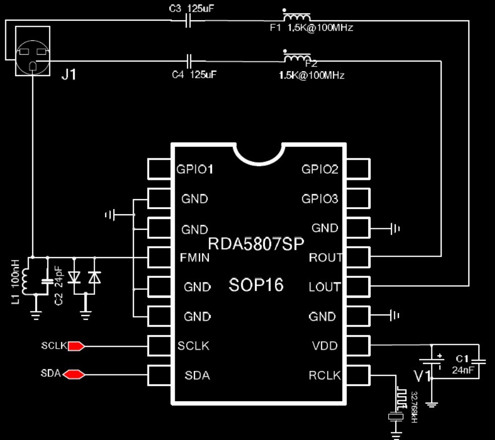
Basic application circuit using I2C is as below from the datasheet.
The three GPIOs are available for user and can be set or reset by writing into specific registers. But once we enable the I2S then these pins can no longer used as GPIOs and start emitting the I2S through these GPIO pins.
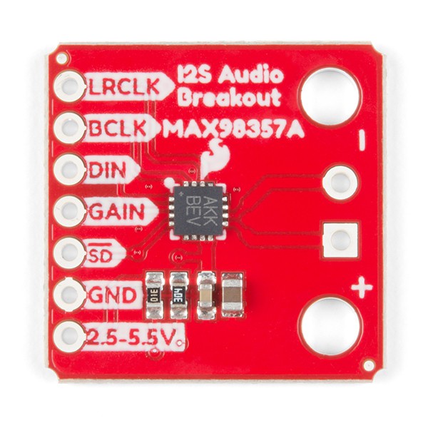
The basic I2S digital audio format as per RDA datasheet is as follows
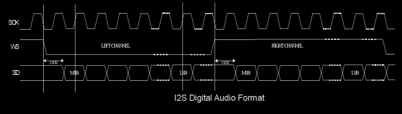
The I2S bus has three lines:
• continuous serial clock (SCK)
• word select (WS)
• serial data (SD)
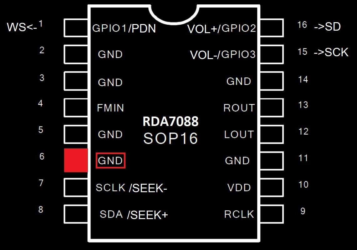
Instead of connecting the pin#6 to VDD, if we connect pin#6 to GND, then the RDA7088 can behave as I²C controlled FM Tuner with RDS and I²S output capable. The above picture gives a idea or feeling how the pins and functions of RDA7088 changes when we connect pin#6 to GND instead of VDD.
I²S OUTPUT:
To enable the I²S output, there are just 3 bits needs to be set
REGister 04H bit#6 I2S_ENABLE - 1
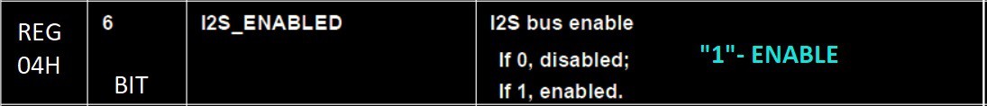
By default this bit is "0". We should enable this bit to "1" for enabling the I²S output.
REGister 06H bit#9 data_signed = "1"
REGister 06H bits[7:4] I2S_SW_CNT[4:0] - 4'b1000 for 48kbps
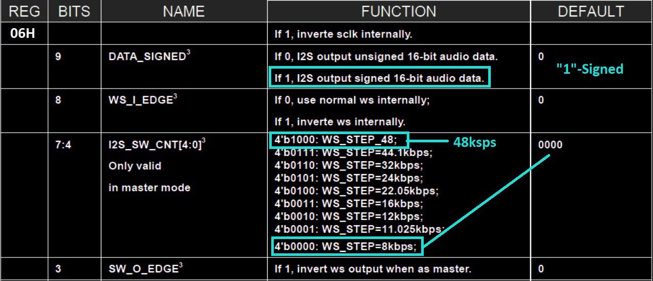
Most of the I²S audio DACs tested supported the signed audio data. Default DATA_SIGNED bit is "0" for unsigned 16-bit audio data. We should enable DATA_SIGNED = "1" for signed 16-bit audio data.
Default...
Read more »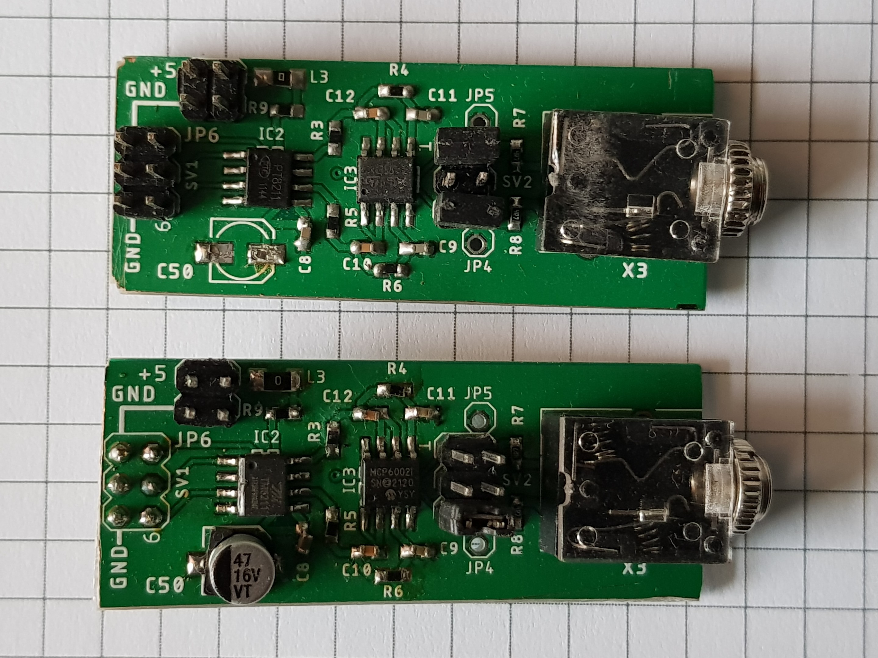
 Florian Wilhelm Dirnberger
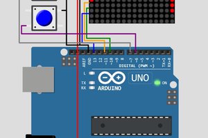
 Michael Möller
 Hulk
Hulk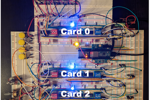
 Andy Birch