 zpekic
(Refer to "Hello World!" example in EMZ1001A assembler for code discussion below)
"Hello World" is expected to show case any new programming language, and EMZ assembly has been resurrected along with the "chip" so it seemed perfect to use it as a default "firmware" that goes inside the 1k ROM.
It simply rotates (in 1 sec intervals) the text on 7seg LED display (DISB instruction), and outputs the ASCII character sequence (plus CR and LF) using OUT instruction. Algorithm is:
- Initialize operating modes (most important is to not float D lines to be able to drive TTY and UART inputs)
- Initialize RAM with the 7seg LED patterns of "HELLo WorLd!" string - this is 12 characters, so remaining 4 are set to zero (no segment lit up)
- Output "HELLO WORLD!" to UART and TTY (each character is a JMS call to a character-specific entry point)
- Refresh the LEDs (run DISB in loop for all BU values)
- Check if 1 second has expired, if no go to step 4 (this keeps LEDs lit!), otherwise continue
- "rotate" values in RAM banks 0 and 1 - this achieves the "scroll every 1s" effect
- go back to step 3 for infinite loop
Weird but clever LAI
As per documentation, only first LAI (Load Accumulator Immediate) instruction in a sequence is executed. There is an internal flag which is set by LAI and reset by any other instruction, and if true, LAI becomes a NOP. This strange but simple trick allows easy implementation of multiple entry points into a subroutine, while saving many instructions jumping over the alternate paths:
GREETINGS:    LBZ 0b11;        // BU = 3, BL = 0
        JMS CRLF;        // empty line
        JMS H;            // output character by characted on D port, with nEXT strobe
        JMS E;
        JMS L;
        JMS L;
        JMS O;
        JMS SPACE;
        JMS W;
        JMS O;
        JMS R;
        JMS L;
        JMS D;
        JMS EXCPOINT;
        JMS CRLF;
...

H:        LAI 0x0F & 'H';    // using EMZ1001A trick that in a sequence of LAIs only 1st one is executed!
E:        LAI 0x0F & 'E';
L:        LAI 0x0F & 'L';
O:        LAI 0x0F & 'O';
D:        LAI 0x0F & 'D';
OUT_4:        RSM 3;        // high nibble is 0b0100 for these ASCII codes
        STM 2;
        JMP OUT_xx00;
4 JMP instructions are saved in the sequence above. In additional trick, characters are grouped by value of upper nibble of ASCII code, and convenient RSM (reset memory bit) and STM (set memory bit) can directly update RAM without disturbing the A register.
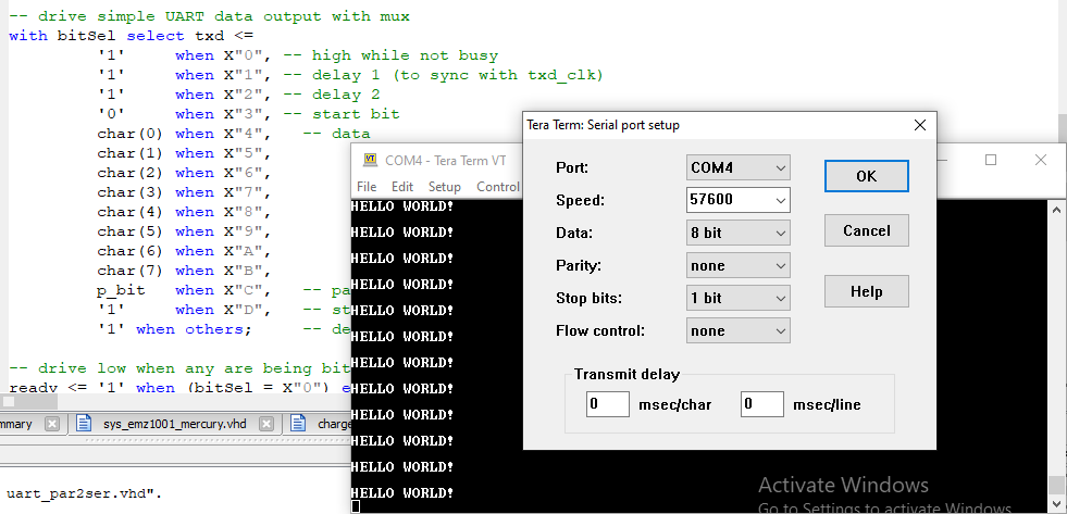
OUT instruction - simple but effective
Both DISB and OUT output 8-bit data on the D bus - when not in float mode and not multiplexed for use as ROM data inputs. The difference is strobing:
- OUT - nEXT goes low during T7
- DISB - nEXT stays high, but A strobes the LED digit (high or low)
Both TTY (to VGA) and UART (parallel to serial) take 8-bit ASCII data, so their input is connected to D, and strobe (inverted) to nEXT. That means 1 OUT sends ASCII character simultaneously to both with the effect of "print" (even a simple unidirectional Centronics interface could be added for a real print), but only if they are both ready as sensed by input line I0 (there is no FIFO buffer between CPU and output devices, so the output speed is effectively limited by baudrate / 16).
CRLF:       LAI CR;
            JMS OUT_0;    // old assembly trick
            LAI LF;
OUT_0:      RSM 3;        // set current RAM location to 0
            RSM 2;
OUT_xx00:   RSM 1;
OUT_xxx0:   RSM 0;
UART_OUT:   OUT;
UART_WAIT:  LAI OUT_READY;  // connected to pins 0, 1 of I inputs
            SZI;            // skip if low
            RT;             // signal high, ready
            JMP UART_WAIT;  // signal low, not ready
Note: more optimal implementation would first check for readiness and then if ready proceed to OUT and return - this way fewer instructions after RT would be blocked, and a simple "parallelization" of CPU operation and 2 output devices operations could be achieved.
DISB - any pattern to LEDs
Somewhat readable text can be represented on 7-segment LED with a certain "font" but that requires each segment to be driven independently. DISB has same multiplexing rules like DISN but directly connects A to D3-D0 and RAM[BU, BL] to D7-D4. The patterns for LED characters are stored in banks 0 (LSN) and 1 (MSN) so A value has to be picked up from bank 0 in each iteration to combine with bank 1:
// ---------------------------------------------------------------------------
.org 0b1110000000;
// Page 14 in the bank is for the subroutines overflow
// ----------------------------------------------------------------------------
DISP_LED_: LAI 12; // start displaying at digit 12
XAE; //
LBE 0b00; // BL = 12, BU = 0
LEDLOOP: LAM 0b01; // A <= M[0, BL], BU = 1
DISB; // direct pattern to D outputs (inverted)
PSL; // prepare digit low (on)
MVS; // update A pins (A[BL] <= '0')
NOP; // delay to keep it lit for a bit
NOP;
PSH; // prepare digit high (off)
MVS; // update A pins (A[BL] <= '1')
LAM 0b00;
XCD 0b01; // next, change column to 0
JMP LEDLOOP;
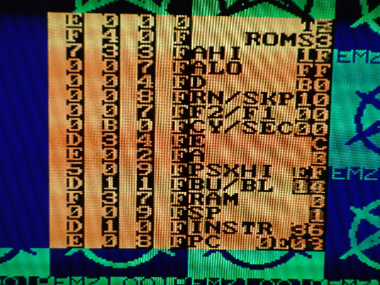
RT;The only remaining piece for scrolling LED display is "rotating" RAM by 1 location in bank 0 and 1 (in sync). This is extremely efficient due to XCI instruction which combines 3 reads, 3 writes, 1 increment and one skip in one 6-bit op-code! The instruction set is really optimized for the processor architecture and multiplies its capabilities.
// ---------------------------------------------------------------------------
		.org 0b1111000000;
//	Page 15 in the bank is the default place for subroutines
// ----------------------------------------------------------------------------
ROTATE:		LAM 0b00;	// A = M[x, 15]
		XCI 0b00;	// BL is now 0
		NOP;
ROTLOOP:	XCI 0b00;	// deposit from previously visited memory cell, increment BL
		JMP ROTLOOP;    // continue until all visited
		RT;
Effect of running ROTATE on banks 0 and 1 can be seen here (note how 73 (pattern for H) moved "down" 2 locations after 2 calls to ROTATE, meaning H (and rest of text) moved left):

The worst about EMZ1001A instruction set is...
... lack of read-only data in program memory (ROM). Using various look-up tables (if there is enough memory for them) can speed up and simplify code significantly. Unfortunately EMZ1001A has no way to pick up any data from ROM and deposit it into the RAM or outputs etc. This means that initializing RAM banks 0 and 1 with 16 LED character patterns had to be done by executing LAI + XCD (exchange with RAM and decrement BU) 32 times. Some optimizations could be possible but that would make the code even more unreadable.
//	---------------------------------------------------------------------------
	.org 0b1101000000;
//	Page 13 for more subroutines
// ----------------------------------------------------------------------------
INITLED1_:	LBF 1;			// RAM bank 1 holds lower nibble of LED patterns
		JMS CLEAR4;		// clear locations 15, 14, 13, 12
		LAI LED_H / 16;	// store and decrement BU, leftmost is H (location 12)
		XCD 0b00;
		LAI LED_E / 16;
		XCD 0b00;
		LAI LED_L / 16;
		XCD 0b00;
		LAI LED_L / 16;
		XCD 0b00;
		LAI LED_O / 16;
		XCD 0b00;
		LAI LED_SPACE / 16;
		XCD 0b00;
		LAI LED_W / 16;
		XCD 0b00;
		LAI LED_O / 16;
		XCD 0b00;
		LAI LED_R / 16;
		XCD 0b00;
		LAI LED_L / 16;
		XCD 0b00;
		LAI LED_D / 16;
		XCD 0b00;
		LAI LED_EXCL / 16;	// rightmost is ! (location 0)
		JMP INIT_DONE;		// store and return
Discussions
Become a Hackaday.io Member
Create an account to leave a comment. Already have an account? Log In.