 mit41301
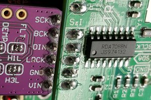
FM tuner RDA7088 is capable of processing RDS information as well apart from I2C bus and I2S output support!
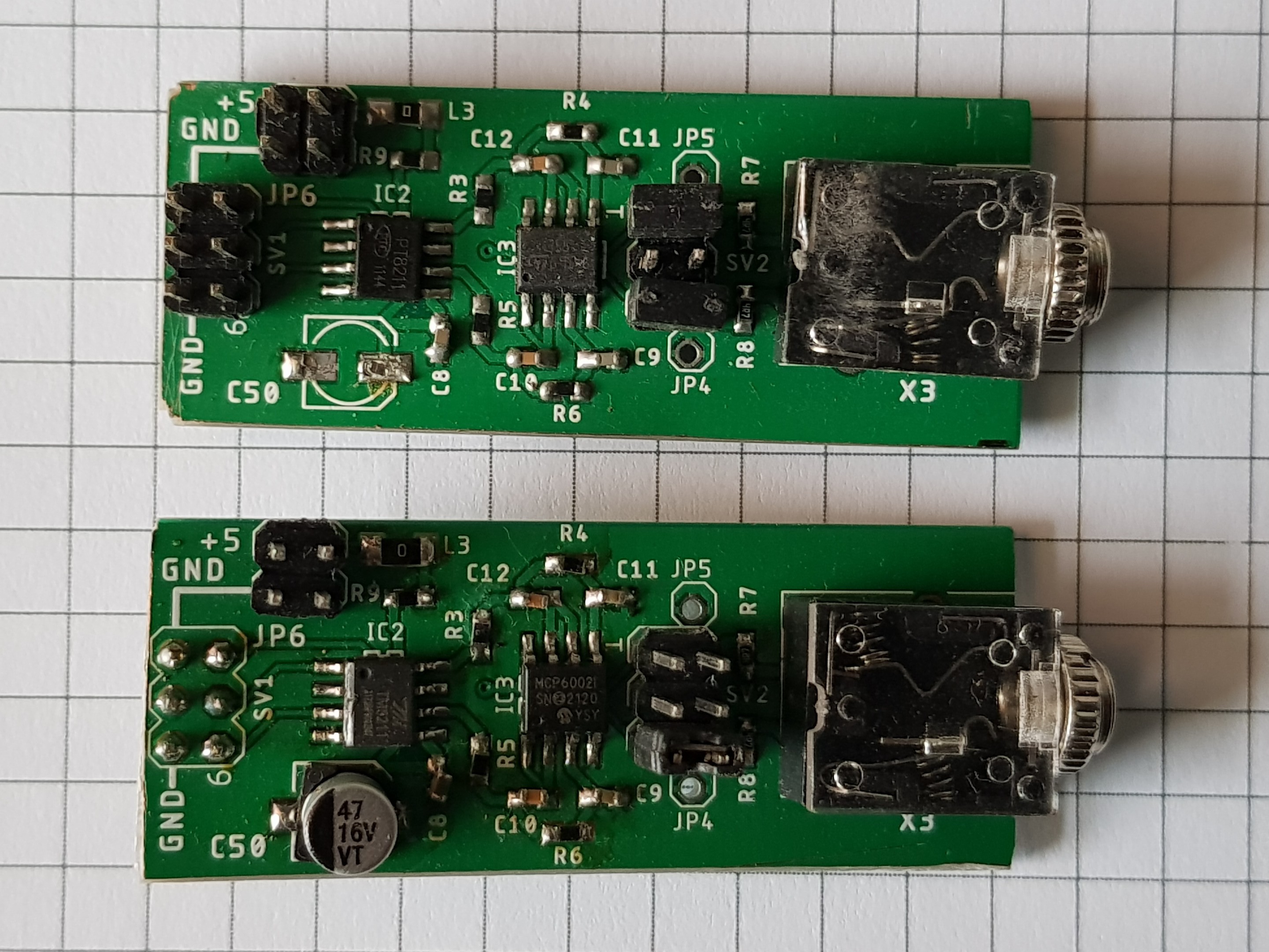
Compared to my I2S output FM tuner project, FM tuner, IR remote control and I2S DAC remains the same.
PIC10F200 replaced by ESP-01 and display module is added(LCD or OLED).
In ESP-01 out of four possible GPIOs only three GPIOs are used. GPIO1 still available for future use.
FM tuner, OLED or LCD and EEPROM IC(24C0X) shares the same I2C bus. EEPROM used to remember the last used channel frequency and volume settings. The GPIO3 input is used for IR remote receiver input(RX) pin.
Both LCD(I2C bus compatible 4 pin type) and OLED(4 pin type) modules were used for testing.
Since with ESP-01 we have enough memory, speed and processing power it is much easier to develop the software using Arduino IDE with readily available libraries.
We can use any FM tuner Arduino library supports RDA Microelectronics tuners. We can easily adopt the OLED or LCD modules from available Arduino libraries. We can easily adopt any available IR remote control Arduino library.
The Wi-Fi feature of ESP-01 is NOT used in the project. We can enable the Wi-Fi feature of ESP-01 for remote access, monitoring and OTA firmware update. Same setup tested with ESP-12, ESP32 and working fine. Since currently we are using just three I/O port pins, decided to use ESP-01.
ESP-01 pin map
GPI00 - SDA(FM tuner + OLED or LCD + EEPROM)
GPIO2 - SCL(FM tuner + OLED or LCD + EEPROM)
GPIO3 - Rx - IR receiver
If we enable the I2S output of RDA7088 the following GPIO pins will be assigned to the I2S signals
PIN# 01 - GPIO1 - WS
PIN# 16 - GPIO2 - SD
PIN# 15 - GPIO3 - SCK
Even if we enable the I2S, still we will be getting the analog output on LOUT & ROUT pins concurrently!
We are using 32.768kHz crystal for RCLK required for the tuner. The RDA7088 tuner supports 12MHz, 13MHz, 19.2MHz, 24MHz, 26MHz & 38.4MHz external RCLK for operation. If we have any of the above frequency readily available or any PLL capable of generating any of the above mentioned frequencies then we can eliminate the 32.768kHz crystal used to generate the RCLK.
REGISTER 04H and 06H details of RDA7088
REG 0x04
/////////////REG:04//////////////////////WR//
  Wire.beginTransmission(0x11);
  Wire.write(0x04);
  Wire.write(0b10001000);
//         -[B#FEDCBA98]-
//             ||||||||______(08)-AFCD AFC disable 0- afc work; 1- afc disabled
//             |||||||_______(09)-SOFTMUTE_EN If 1, softmute enable
//             ||||||________(10)-RDS_FIFO_CLR 1 = clear RDS FIFO //RDSR _MODE???
//             |||||_________(11)-DE De-emphasis 0 = 75 μs; 1 = 50 μs
//             ||||__________(12)-RDS_FIFO_EN 1 = RDS fifo mode enable.
//             |||___________(13)-RBDS 1 = RBDS mode enable 0 = RDS mode only
//             ||____________(14)-STCIEN 1 = IINT ENA : STCIEN = 1 will generate low pulse on GPIO2
//             |_____________(15)-RDSIEN 0 = Disable 1 = Enable Setting STCIEN = 1 will generate a low pulse on GPIO2
  Wire.write(0b01000000);     //  Wire.write(0b01000000);
//         -[B#76543210]-
//             ||||||||_______(0)-GPIO1[1:0] 00 = High impedance 01 = Reserved
//             |||||||________(1)-GPIO1[1:0] 10 = Low 11 = High
//             ||||||_________(2)-GPIO2[1:0] 00 = High impedance 01 = Interrupt (INT)
//             |||||__________(3)-GPIO2[1:0] 10 = Low 11 = High
//             ||||___________(4)-GPIO3[1:0] 00 = High impedance 01 = Mono/Stereo indicator (ST)
//             |||____________(5)-GPIO3[1:0] 10 = Low 11 = High
//             ||_____________(6)-I2S_ENABLED 1-ENABLED : 0-DISABLED
//             |______________(7)-GPIO1_INT_EN???
  Wire.endTransmission(); // stop transmitting
/////////////REG:04//////////////////////END//
REG 0x06
/////////////REG:06//////////////////////WR//
  Wire.beginTransmission(0x011);
  Wire.write(0x06);
 Wire.write(...
Read more »

 samfallday
 biemster
 Ethan Durrant