Sagar 001
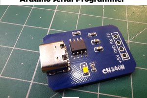
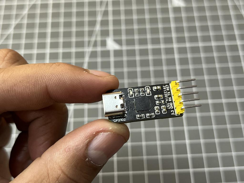
There are a lot of programmers available which helps to covert the USB data into UART form. Which then allows to flash the complied data into microcontroller’s memory. But some of the programmers are compatible with Arduino and has DTR reset pin. Another big problem is that these programming boards has an old USB ports which are not recommended in this era of tech. So I decided to make my own fully Arduino compatible programmer and eliminated the USB problem. I am using CP2102N chipset which usually comes in QFN package and USB-C for better connections and usability.
Here I am using Custom parts placement service, SMT assembly service from JLCPCB. Because QFN package is not available in my region also it is very hard to solder this SMT IC. So I tried JLCPCB SMT service, you can choose the parts and quantity of PCB. Here I ordered only 2 assembled PCB which cost me around $10, including parts, soldering and placement cost. If you want to order only PCB then it is $2 for 5 pieces.
CP2102N:
These highly-integrated USB-to-UART bridge controllers provide a simple solution for updating RS-232 designs to USB using a minimum of components and PCB space. CP2102N includes a USB 2.0 full-speed function controller, USB transceiver, oscillator, and Universal Asynchronous Receiver/Transmitter (UART) in packages as small as 3mm x 3 mm. No other external USB components are required for development. All customization and configuration options can be selected using a simple GUI-based configurator. By eliminating the need for complex firmware and driver development, the CP2102N devices enable quick USB connectivity with minimal development effort
Components required:
1) CP2102N
2) 100nf capacitor
3) USB type C
4) 1k, 10k resistors
5) 0603 SMD LED and Pin headers
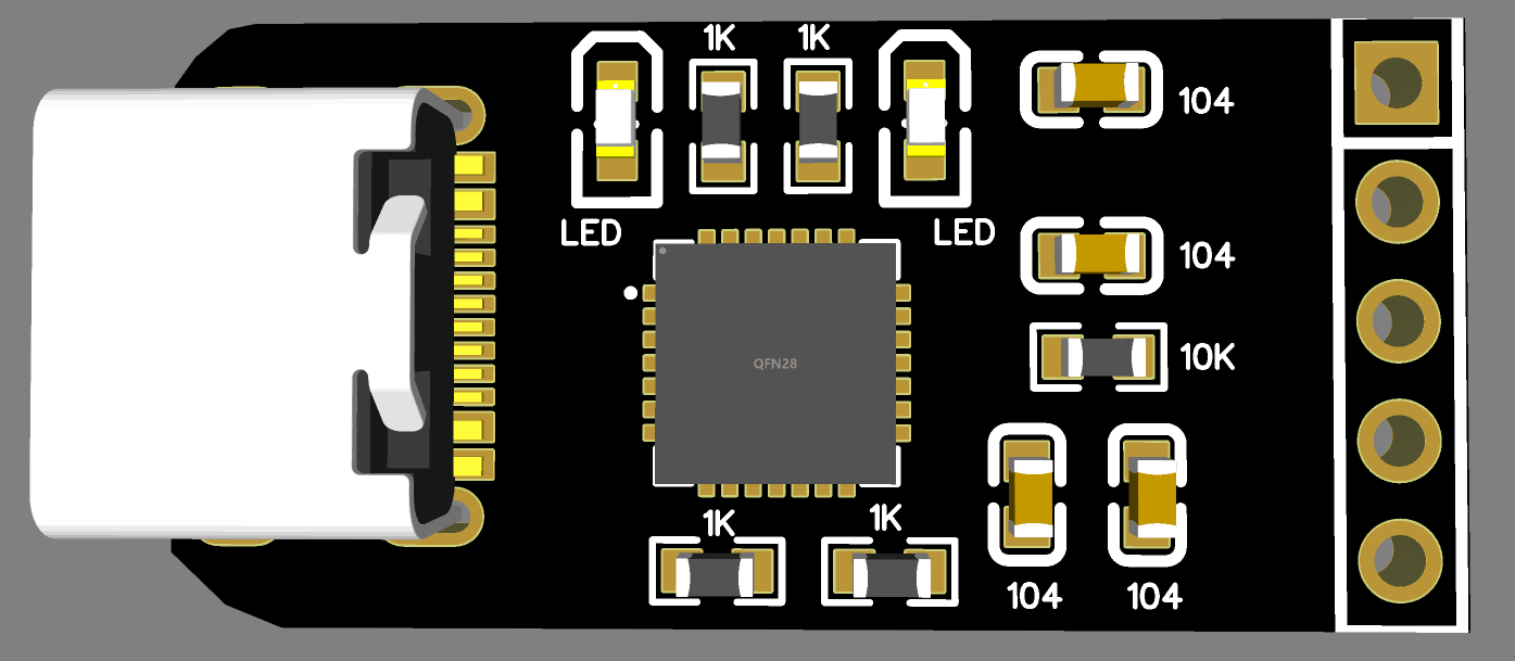
Circuit diagram:
I designed the circuit diagram using EasyEDA and then prepare the Gerber files from it. You can see the modified layout given below. For all the designing requirements you can follow the datasheet of this specific IC.
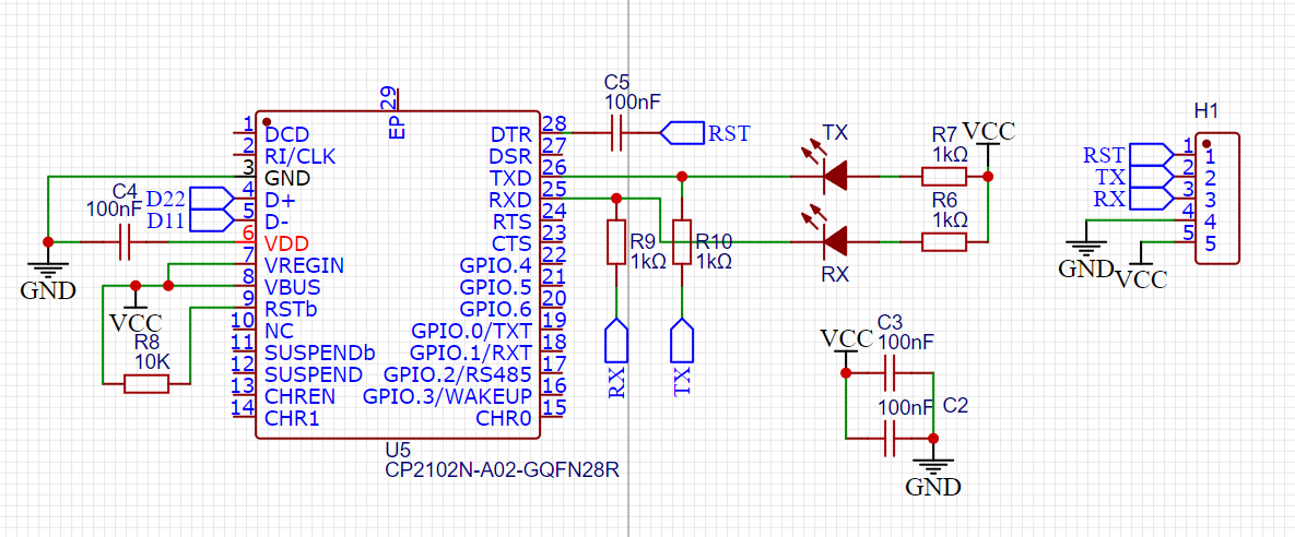
Here the LEDs are connected between RX and TX pins of the IC which help to demonstrate the flashing action. The data input is given through the USB type C port. In addition a 10k resistor is required at the RST pin. 1uf coupling capacitors are placed near to the IC and between the DTR and reset pin. The serial headers are placed one side of the PCB having VCC, GND, TX, RX and DTR pin.
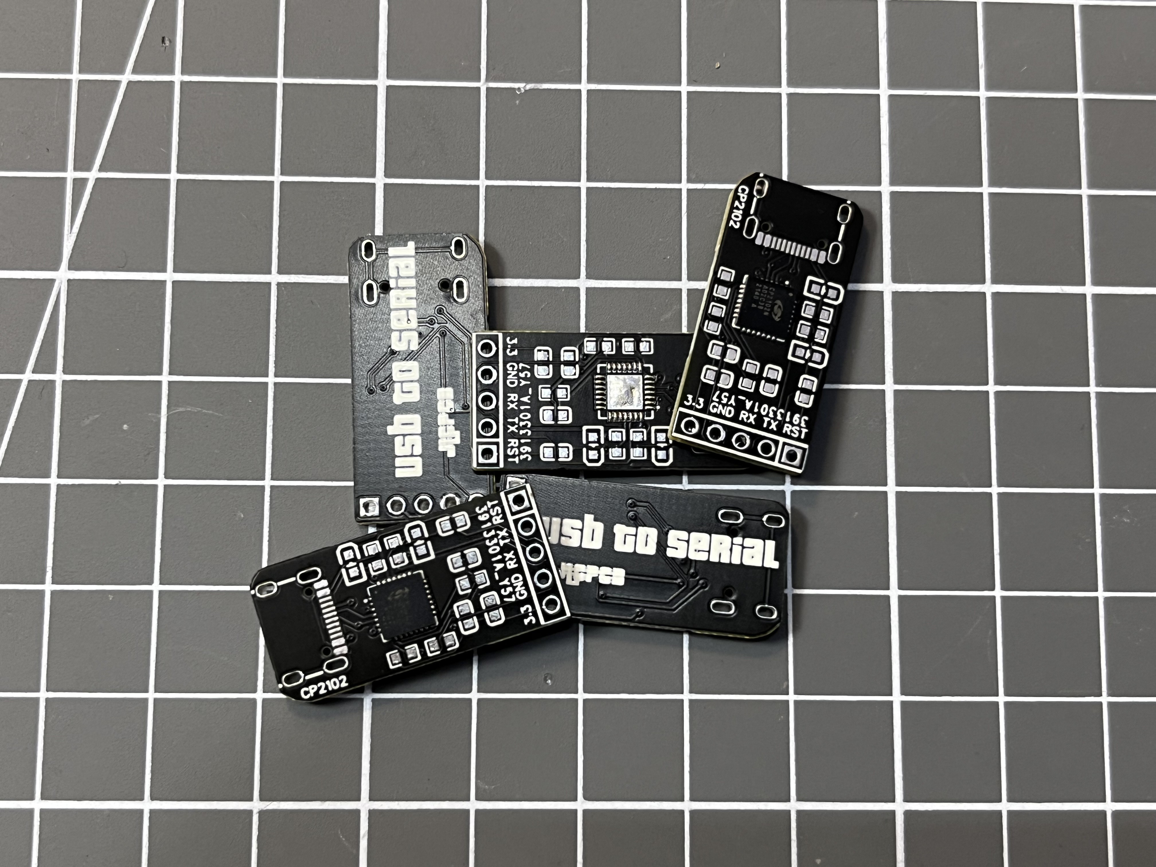
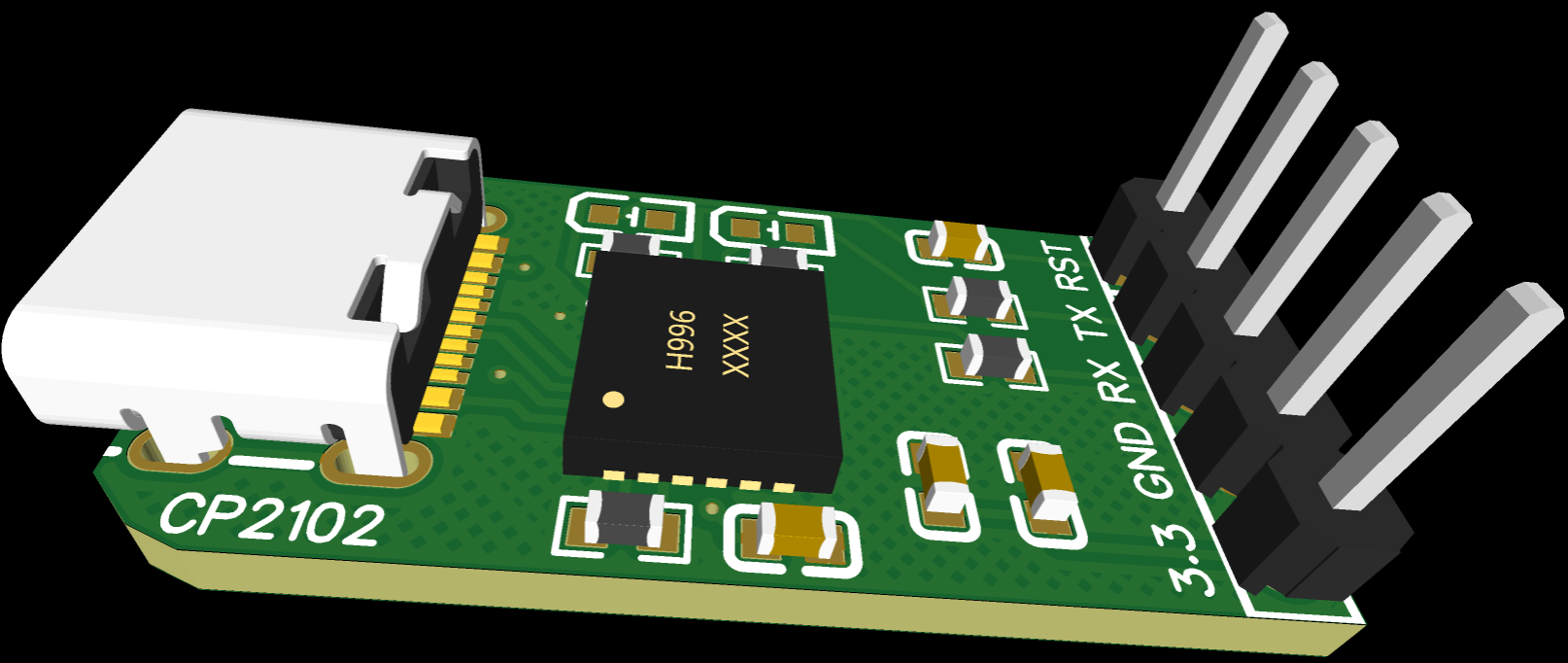
PCB designs and Gerber:
The PCB is designed using custom SMT assembly service form JLCPCB and some small components are soldered by me. You can download the required Gerber files from here.
JLCPCB is the China’s leading PCB manufacturer and nowadays dealing in a lot of PCB related new service. You can try 4–6-layer precision PCB, 5-18 Layer ultra-precision PCB, SMT assembly, Full PCBA, Stencil and 3-D printing services. Sign-up now using this link and get $54 new user coupons.
Assembly and soldering:
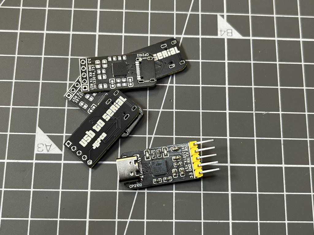
I ordered 5pcs of these boards in which 2 are assembled, then I start soldering rest of the components, you may find whole the list with values here. The main challenge for me to solder the type C port properly. You may order the full assembly BOM and CPL files are shared below.
Drivers for CP2102:
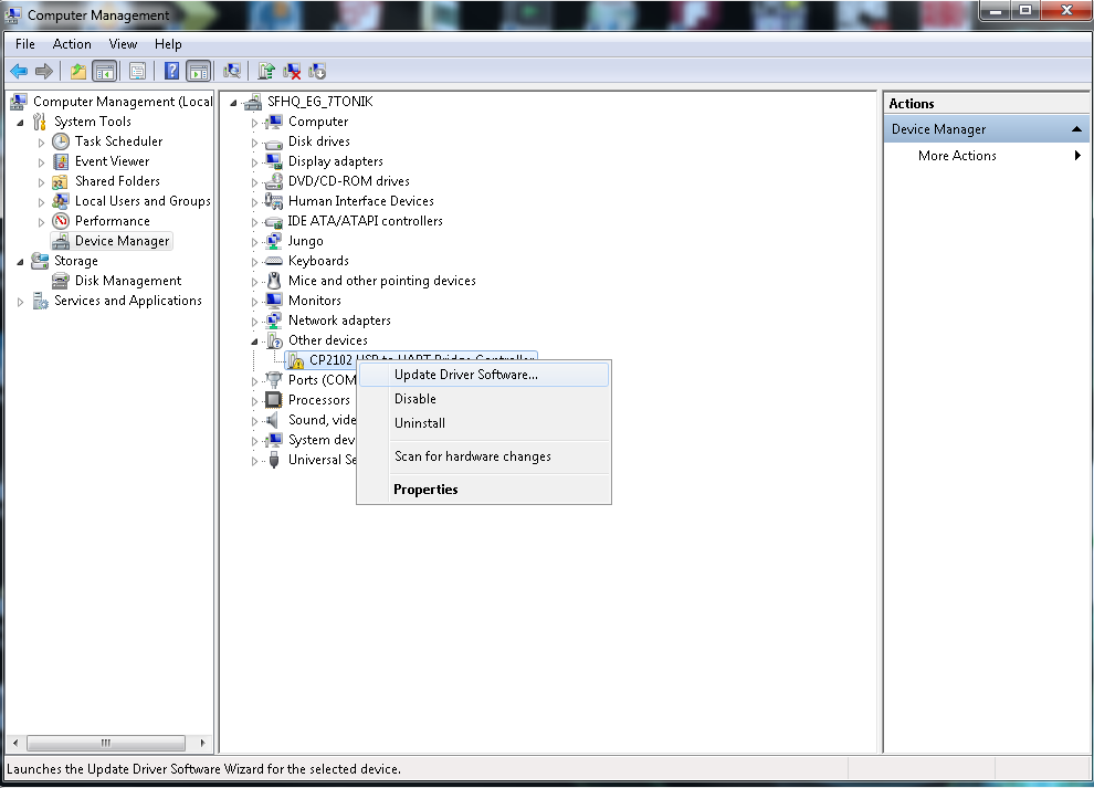
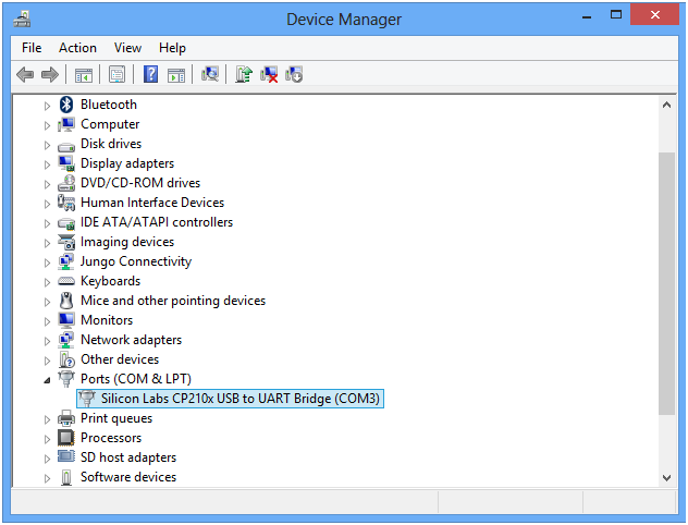
Now to setup the interface of computer COM port with CP2102 hardware, we need a software driver which can recognise the device and then help the IDE to upload the code. You can download the drivers from here and then locate the position of installed drivers after going into device manager for proper working.
Connection with Arduino:
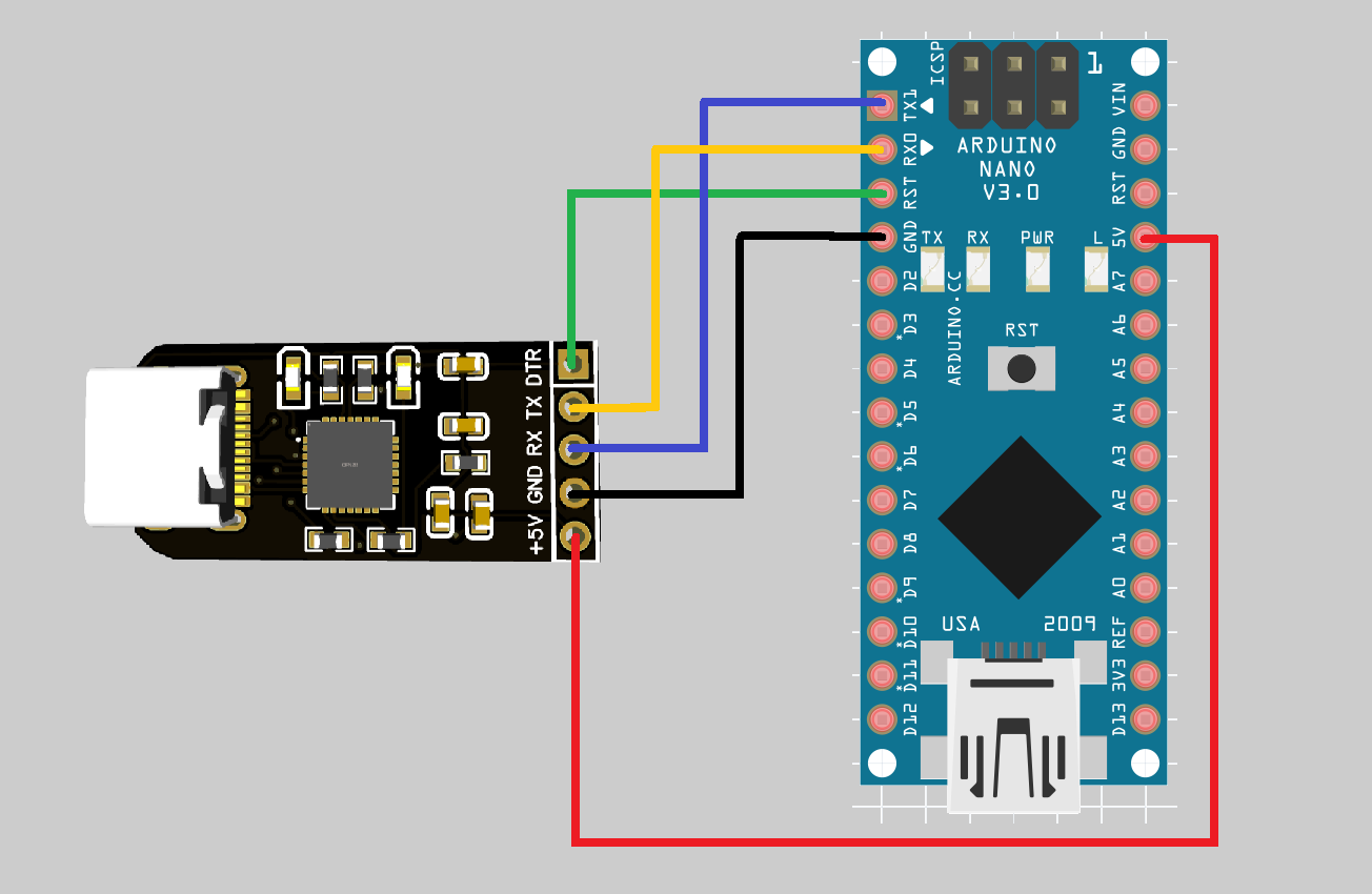
The connection of CP2102N with Arduino is quite easy and simple, Connect 5v to VCC, GND is common, TX to RX, RX to TX and DTR to reset pin of Arduino.
Working and testing:
After updating the driver settings you can see the cp2102 name in the ports section inside device manager of your computer. Then make all the connection with Arduino according to the above given schematics. And choose the right COM port inside Arduino IDE, select...
Read more »
 Lithium ION
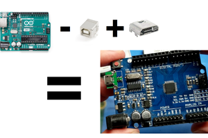
 sjm4306