 electronicsworkshops
Introduction
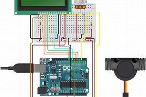
In this tutorial, we will measure the water flow rate and volume using an Arduino and a Flow Sensor. In this circuit, the water flow sensor is linked to an Arduino and an LCD, which is programmed to display the volume of water that has passed through the valve. The water flow sensor used in this circuit is an S201, which uses a hall effect to sense the flow rate of the liquid.
If You want similar Projects CLICK HERE
PCB Manufacturer
The pcb of this project is manufactured by JLCPCB. The reasons to choose JLCPCB for pcb manufacturing are:
- Higher Quality
- Lower Cost
- Faster Delivery
If you want to order your pcb from jlcpcb just go through the link below:

Bill Of Materials
| SN | COMPONENTS NAME | DESCRIPTION | QUANTITY | |
|---|---|---|---|---|
| 1 | Arduino Board | Arduino UNO R3 Development Board | 1 | https://amzn.to/3UBnwTO |
| 2 | LCD Display | 16x2 LCD Display | 1 | https://amzn.to/3UhShNH |
| 3 | Potentiometer | 10K | 1 | https://amzn.to/3NMyzag |
| 4 | Water Flow Sensor | YFS201 Hall Effect Water Flow Sensor | 1 | https://amzn.to/3XEcnDV |
| 5 | Water Pipe | normal | 1 | https://amzn.to/3EHvcxy |
| 7 | Connecting wires | jumper wire | some | https://amzn.to/3fMoSw7 |
| 8 | Breadboard | Normal | 1 | https://amzn.to/3FUQlXe |
YFS201 Water Flow Sensor
The sensor has 3 wires RED, YELLOW, and BLACK as shown in the figure below. The red wire is used for supply voltage which ranges from 5V to 18V and the black wire is connected to GND. The yellow wire is used for output(pulses), which can be read by an MCU. The water flow sensor consists of a pinwheel sensor that measures the quantity of liquid that has passed through it.

The working of the YFS201 water flow sensor is simple to understand. The water flow sensor works on the principle of hall effect. Hall effect is the production of the potential difference across an electric conductor when a magnetic field is applied in the direction perpendicular to that of the flow of current. The water flow sensor is integrated with a magnetic hall effect sensor, which generates an electric pulse with every revolution. Its design is in such a way that the hall effect sensor is sealed off from the water, and allows the sensor to stay safe and dry.
The picture of the YFS201 sensor module alone is shown below.

To connect with the pipe and water flow sensor, I used two connectors with a female thread as shown below.

According to YFS201 Specifications, the maximum current it draws at 5V is 15mA, and the working flow rate is 1 to 30 liters/minute. When the liquid flows through the sensor, it makes contact with the fins of the turbine wheel, which is placed in the path of the flowing liquid. The shaft of the turbine wheel is connected to a hall effect sensor. Due to this, whenever water flows through the valve it generates pulses. Now, all we have to do is to measure the time for the pluses or to count the number of pulses in 1 second and then calculate the flow rates in liter per hour (L/Hr) and then use simple conversion formula to find the volume of the water which had passed through it. To measure the pulses, we are going to use Arduino UNO. The pic below shows you the pinout of the water flow sensor.

Water Flow Sensor Calculation
As you know,
1 Litre = 1000 mL
So, the range of this sensor is 300mL to 6000mL per minute.
At 1000mL you get 5880 pulses, but is that over a minute otherwise over a second its 5880/60 = 98 Hz square wave which has a period of 1/98 = 10.2 milliseconds.
For 1mL you calculate 5880/1000 = 5.88/60 = 0.098Hz with a period of 10.2 seconds. In the programming, I will be using the pulsein to measure the time of a pulse.
Connections
The connection of the water flow sensor and LCD(16×2) with the Arduino is given below in table format. Note that the pot is connected in between 5V and GND and pot’s pin 2 is connected with the V0 pin of the LCD.

 hIOTron
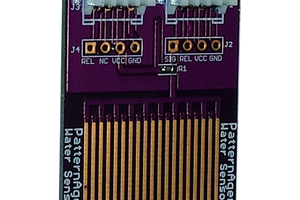
 Pattern Agents
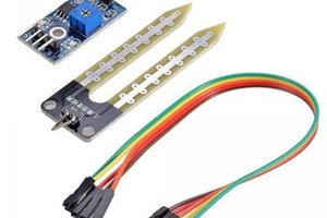
 akanzler007
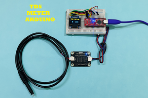
 Lithium ION