I decided to make a beautiful animated (flip) clock with big digits, which is synchronized over the Internet. The basis for my project was the code of Pawel A. Hernik from which I removed the part that shows the weather information and currency rate. I did this to make the code as simple as possible and more understandable.I also made the following changes to adjust to my project:
- Display of 7 instead of 6 matrices
- Clock and seconds blinking dots are moved for 4 LEDs to the right
- Texts "connecting" and "getting data" are displayed in the middle of the screen
- An increased period of time between two data collections from a server
- UTC offset changed to "1" for my country
We must first install the ESP8266 board on Arduino IDE, and then upload the code on the appropriate board and port. The code cannot be compiled on the latest version of the ESP board (2.5.0), so we must install an older version (2.4.2).
On the same hardware with minimal changes, it can be installed more codes.For example, in the video below, you can see a YouTube channel Subscriptions and views counter.as can be seen from the picture, the circuit is very simple

A smart clock can display much more information than a traditional digital clock. Most importantly, a smart clock is connected to the network or internet and can be controlled through a smartphone or PC. You can also display whatever text or information on the smart clock.

In this guide, we will build a smart DIY Wi-Fi-based clock using an ESP8266 microcontroller, and MAX7219 4x8x8 LED matrix. You may use it to display time, date, temperature, humidity, desired text, alerts, Instagram followers, YouTube subscribers, views, animated texts, emoji, and other information with just a few taps.
- Close the Boards Manager window and navigate to Sketch > Include Library > Manage Libraries. Search and install the following libraries.
- PubSubClient
- MD_MAX72XX
- MD_Parola (with dependencies)
Alternatively, you may also these libraries as a .zip file and extract them in the Documents > Arduino > libraries folder.
Step 2: Compile and Flash the Firmware
- Download the Pixel-led MQTT Panel project from GitHub and extract it in the Documents > Arduino folder.
- Open the extracted folder and double-click on pixel_led_mqtt_panel.ino file.
- Go to Tools > Boards > ESP8266 Boards (x.x.x) and select NodeMCU 1.0 or LOLIN(WEMOS) D1—based on the board you are using for this project.
- Select the COM port
- Then make the following changes in the pixel_led_mqtt_panel.ino sketch.
- Enter your Wi-Fi name, password, and OTA password.
- Enter the MQTT server IP, username, and password.
Display Information on the Smart Clock
The smart clock is ready to display whatever text or sensor data you want to display on it via MQTT topics. You can use any MQTT client app to send JSON data for display on the smart clocks. To automate the clock, you can install and set up a Home Assistant server with an MQTT broker and NodeRed on a Raspberry Pi.
You can then use it to display various sensor information and status on the DIY smart clock. To learn more about the topic and animations you can use with the clock, refer to the project on GitHub.
Meanwhile, you can use the following NodeRed sample flow, import it into your NodeRed and edit it according to your sensors to display desired data.

MAX7219 is a popular matrix display that you can control through Arduino boards or ESP8266 WIFI-based microcontrollers, such as NodeMCU and D1 Mini, to display desired information or animations.
This DIY guide used a 4-in-1 MAX7219 matrix to build a smart clock. More than that, it can also be used as a notification panel to display information, such as room temperature, humidity, tank water level, energy usage, and any data or information received via MQTT topics.
If you have set up a Home Assistant or any other home automation server at your home, you may integrate this smart MQTT clock panel to fetch and display all the information received through various sensors and devices you may have installed in your home and integrated with Home Assistant.
I used ws2812 Neo pixel led, which comes with integrated ic so that we can address each segment separately. Not only the LEDs are addressable but also the color can be changed per pixel changing the digital value between 0-255(8-bit value).

This led comes with 4 pins, the configuration of pins can be seen in the picture mentioned above. Also, these Led’s come with Data IN and Data OUT function, which make them more interesting and through this we can join them to show text or data.
Making 7 segment display using neo pixel led:
To make the panel, first we have to take a closer look on actual lcd. So that we can copy the arrangement of segments and design a code for that.

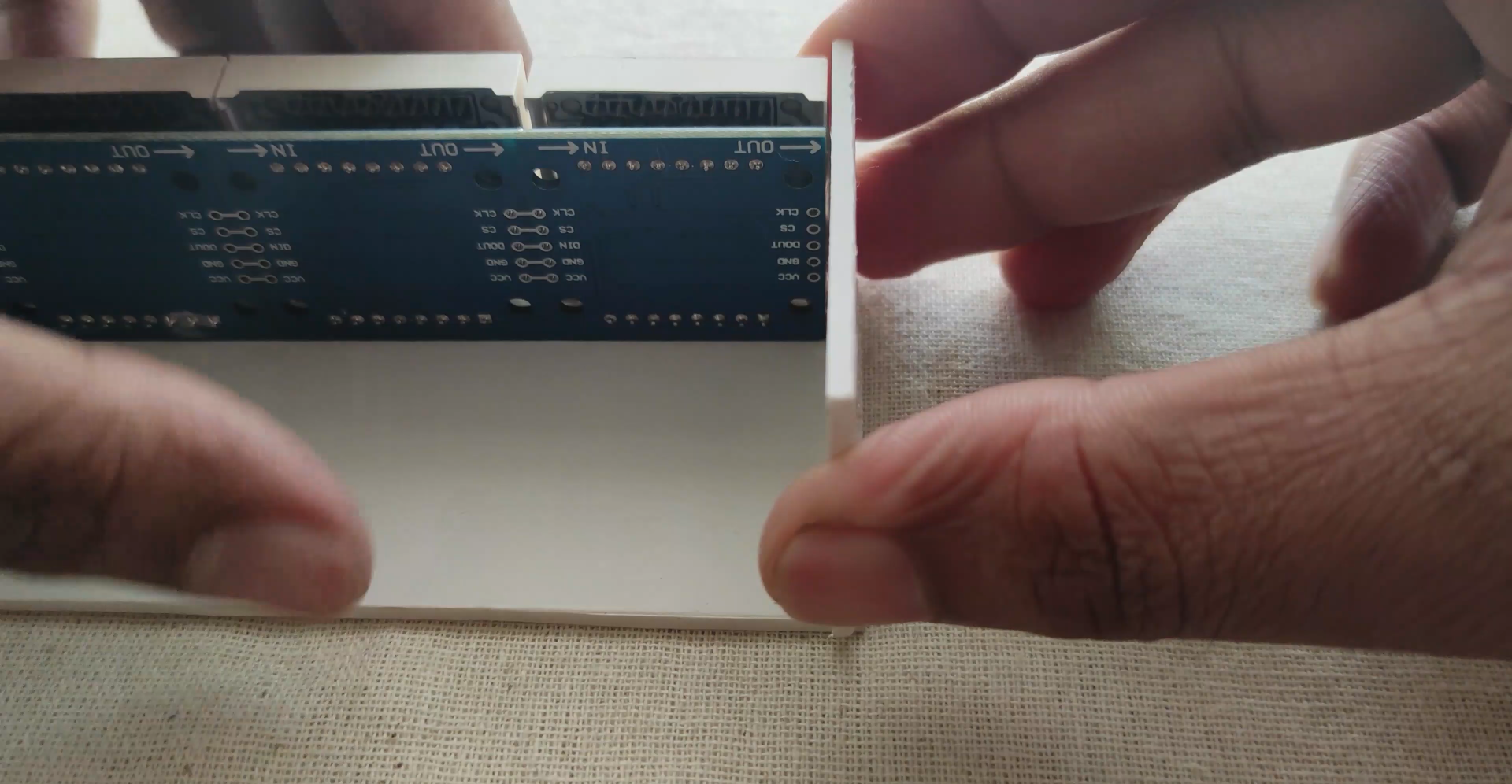
So here, segments are named as A, B, C…… to G, so to connect all the segments we use series data and parallel power method. All the power lines, GND and VCC are joined in parallel to all the led’s. Data OUT is supplied to Data IN of next Led in series. Always connect Dout of first panel to Din of second.
Connect the button pin 12 to 5volt using a 10k resistor and the other end to GND. Means when the button pin is pull down to GND, Display will show temperature readings. The code will also work without this Temperature sensor, so if you want to keep it simple there is no need of these connections.
2) Brightness control using LDR sensor at pin A0.