In this project/tutorial, we are going to discuss how we can build a simple yet very helpful device in managing our lives, a digital clock. While there are digital clocks nowadays that you can set by just connecting to the internet, I decided to use a real-time clock (RTC) because: (1) Obviously, it operates even without internet connection. (2) It is inexpensive. (3) It consumes very little amount of power. (4) and so that we can see how it works. This is going to be a very long tutorial so we are going to split this into three parts. In this part, we will discuss the hardware, in the second part the software, and in the last part we will test the digital clock. So now, let’s check first the components that we need to create a digital clock
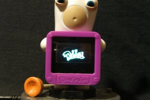
MAX7219 LED matrix, the time, picked with NTP from web, and every 30 seconds shows the temperature and the humidity measured by the DTH11 sensor. The display light also changed based on the light that the photoresistor measures so even if it's day or night you can read time and temperature properly.
I decided to make a beautiful animated (flip) clock with big digits, which is synchronized over the Internet. The basis for my project was the code of Pawel A. Hernik from which I removed the part that shows the weather information and currency rate. I did this to make the code as simple as possible and more understandable.I also made the following changes to adjust to my project:
- Display of 7 instead of 6 matrices
- Clock and seconds blinking dots are moved for 4 LEDs to the right
- Texts "connecting" and "getting data" are displayed in the middle of the screen
- An increased period of time between two data collections from a server
- UTC offset changed to "1" for my country
We must first install the ESP8266 board on Arduino IDE, and then upload the code on the appropriate board and port. The code cannot be compiled on the latest version of the ESP board (2.5.0), so we must install an older version (2.4.2).

1. ATmega328P-PU, 28-pin IC Socket, 2pcs. 0.1uF Ceramic Capacitors, 16MHz Crystal, 2pcs. 22pF Ceramic Capacitors, 10kΩ Resistor (Minimal/Standalone Arduino Uno)
2. DS3231 Precision Real-Time Clock (RTC) Module
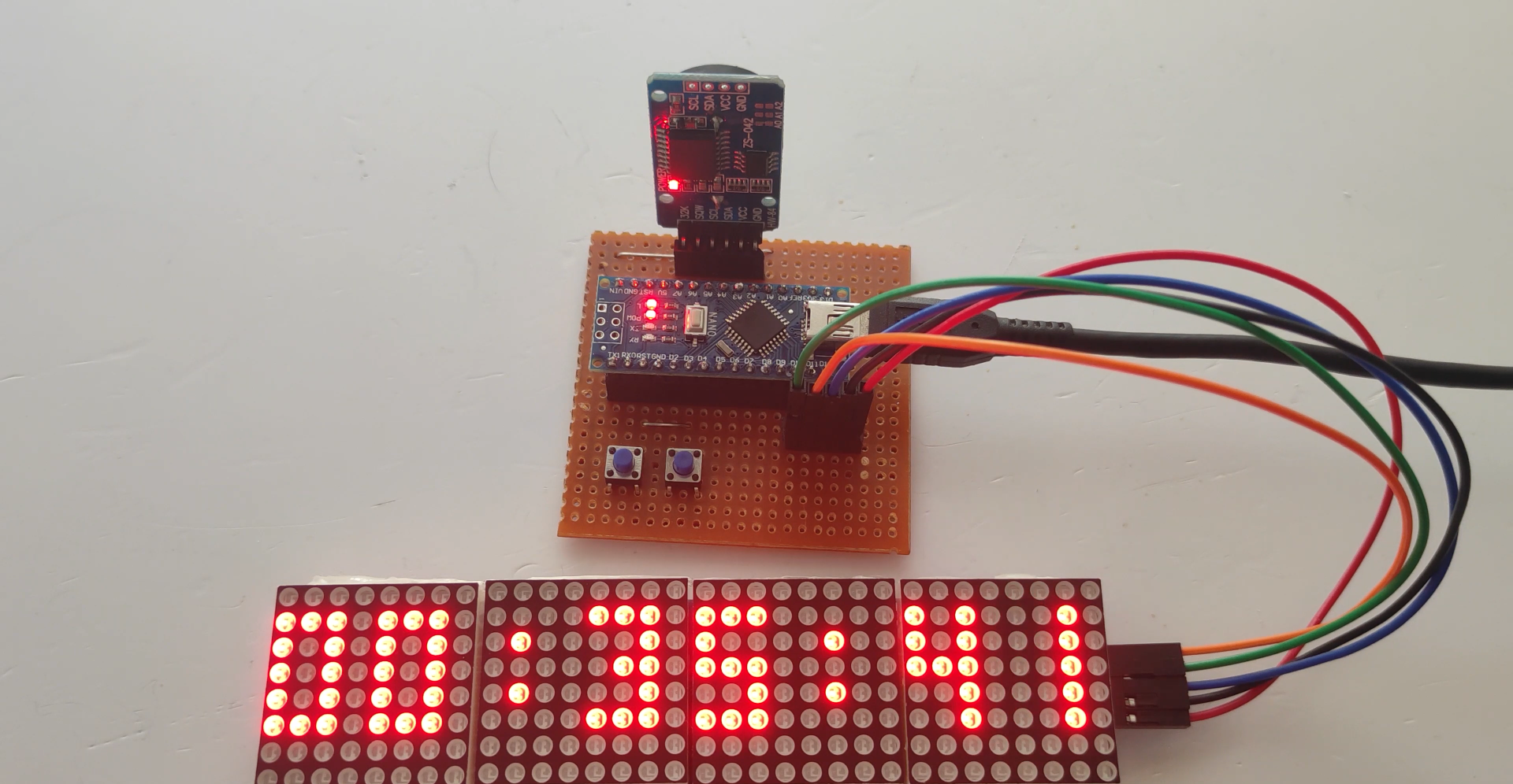
3. 2pcs. 4-in-1 MAX7219 Dot Matrix LED Display Module (Female-to-Female Jumper Wires included)
4. 5pcs. 12mm Tactile Switches
5. 2N3904 BJT & 1kΩ Resistor
6. 2pcs. 470uF Electrolytic Capacitors
7. Male and Female Headers
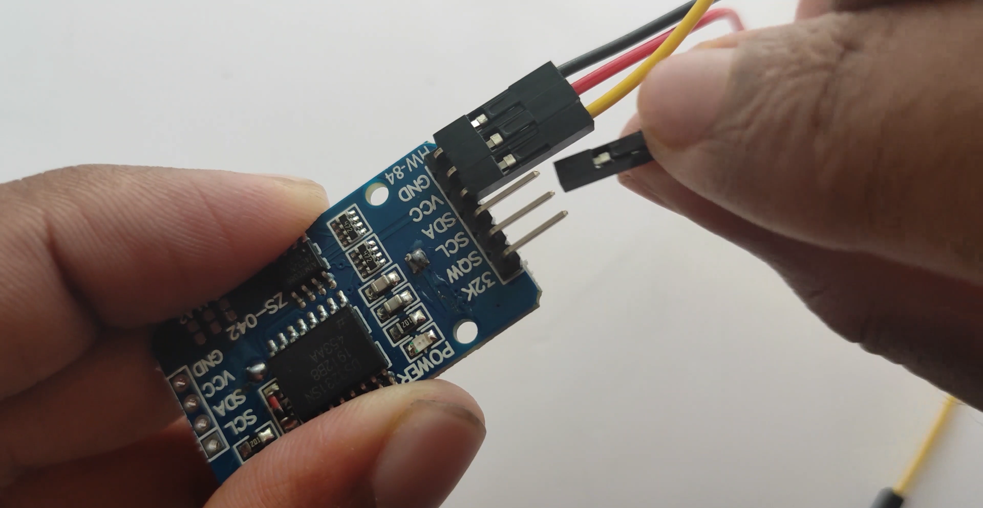
The DS3231 is an I2C RTC device that maintains accurate timekeeping even when main power is interrupted by incorporating a backup battery. It maintains seconds, minutes, hours, day, date, month, and year information as long as the backup battery is in good condition. If the backup battery is removed when main power is not present, the time and date will be reset to its default values so you will need to set it again.
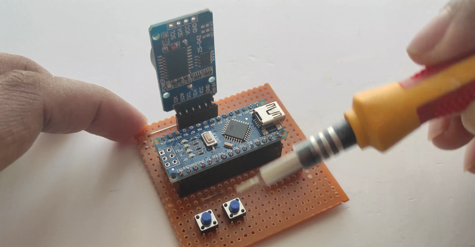
So the main components for this digital clock are the minimal Arduino Uno (standalone Arduino Uno), DS3231 RTC module, and the MAX7219 dot matrix LED display modules. With these three components, we can already display the time and date. However, we won’t be able to set the clock’s time and date unless we reprogram the microcontroller (MCU) again. So I’ve added tactile switches so that we can set the time and date without reprogramming the MCU and other components to make the digital clock stable. Now, let’s check the hardware connections.
So this is the DS3231 RTC module that I used. It’s very common and you can easily purchase it online. The bigger IC in the image is the DS3231 and the smaller IC below it is the AT24C32 which is an EEPROM in case you need to store some values. Good thing about this module is that you don’t need to use external pull-up resistors anymore as it already has on-board 4.7kΩ pull-up resistors connected to the I2C lines. Also, the module includes a 2032 battery holder. As you can see in the image, we have a CR2032 battery there.
However, one thing that I wish they didn’t include in this board...
Read more »
 Randy Elwin
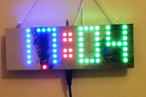
 David Hopkins
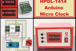
 mircemk