 Josh
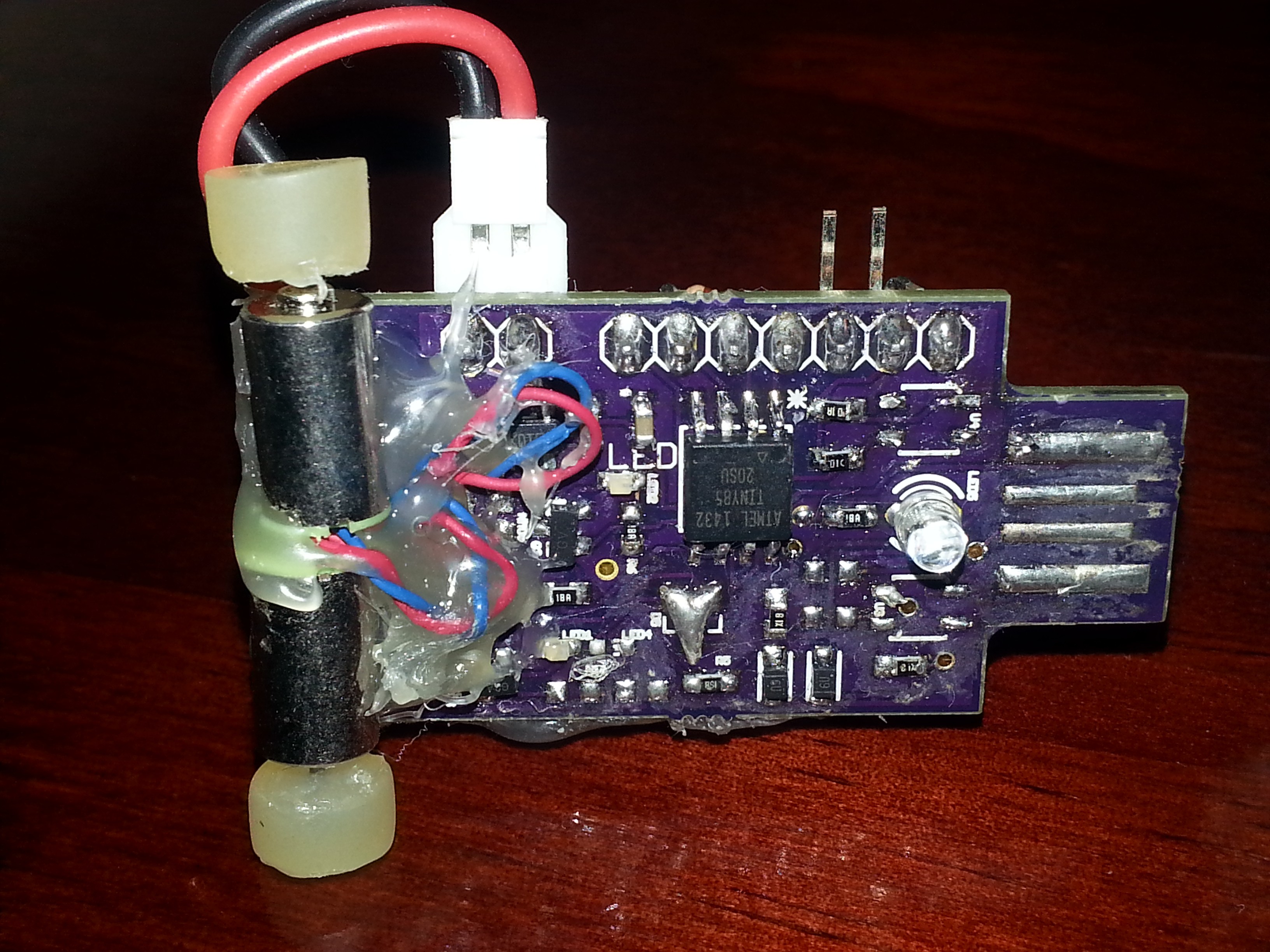
JoshOriginal Design
The image below depicts my very first attempt at making this miniature line following robot. At the time, I did not plan on expanding much further than making a similar obstacle avoidance robot. However, I felt there was way too much potential in this little guy to let him sit and waste away. That is when this project truly started. I took a look at what went wrong with this design and how I could improve upon it. Several ideas came to mind, but ultimately, I chose to develop a base / shield design.
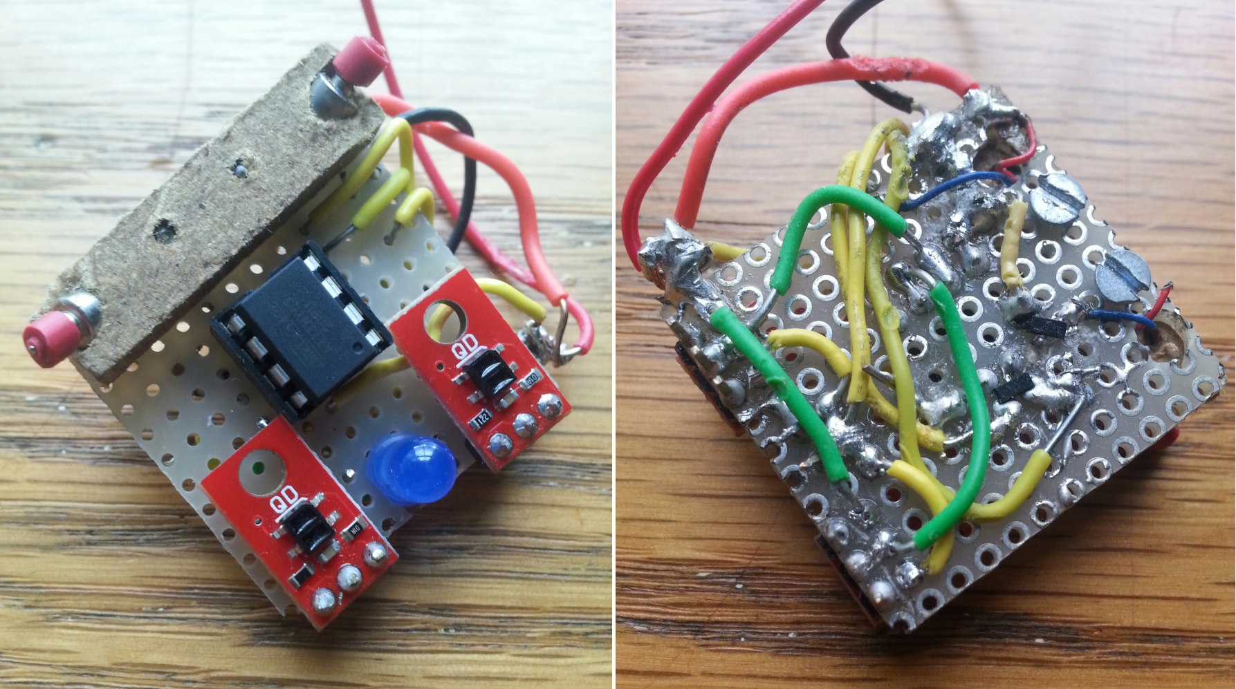
The Drawbacks:
Programming was done externally by removing the Attiny85 Chip, it had no charging capabilities, and major design criteria were not considered such as reliability and reproducibility.
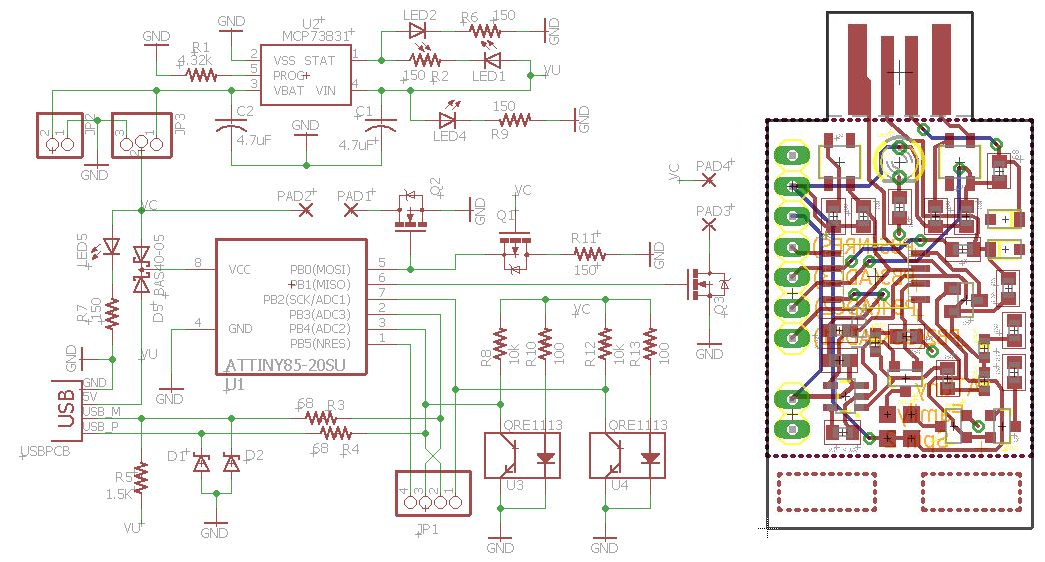
Initial PCB Design - Spin 1
Over the summer, I worked on improving this design. From the blobs of solder and tangle of wires shown above, I created my first PCB shown in the design below. I incorporated an on-board USB programming port, a larger battery, 3D printed motor mounts, and an SPDT power switch.
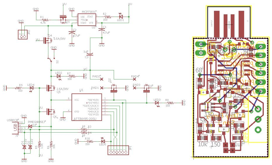
The Drawbacks:
Some of the components I ordered did not work, the electronics to switch between USB power and battery power were wrong, the SPDT switch was too big, and the motors I had were not strong enough to move the robot anymore.
Unsure why the programming aspect did not work with the components I had chosen, I used a breadboard and some spare components to build the bare minimum circuit needed to test the programmer (Basically a Digispark).
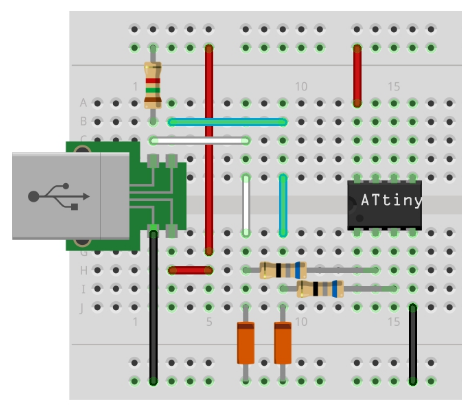
In hindsight, I should have done this first with more aspects of the design before implementing a PCB design...
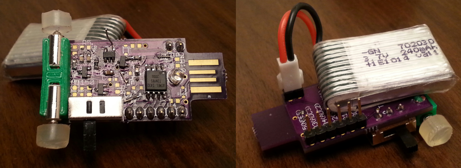
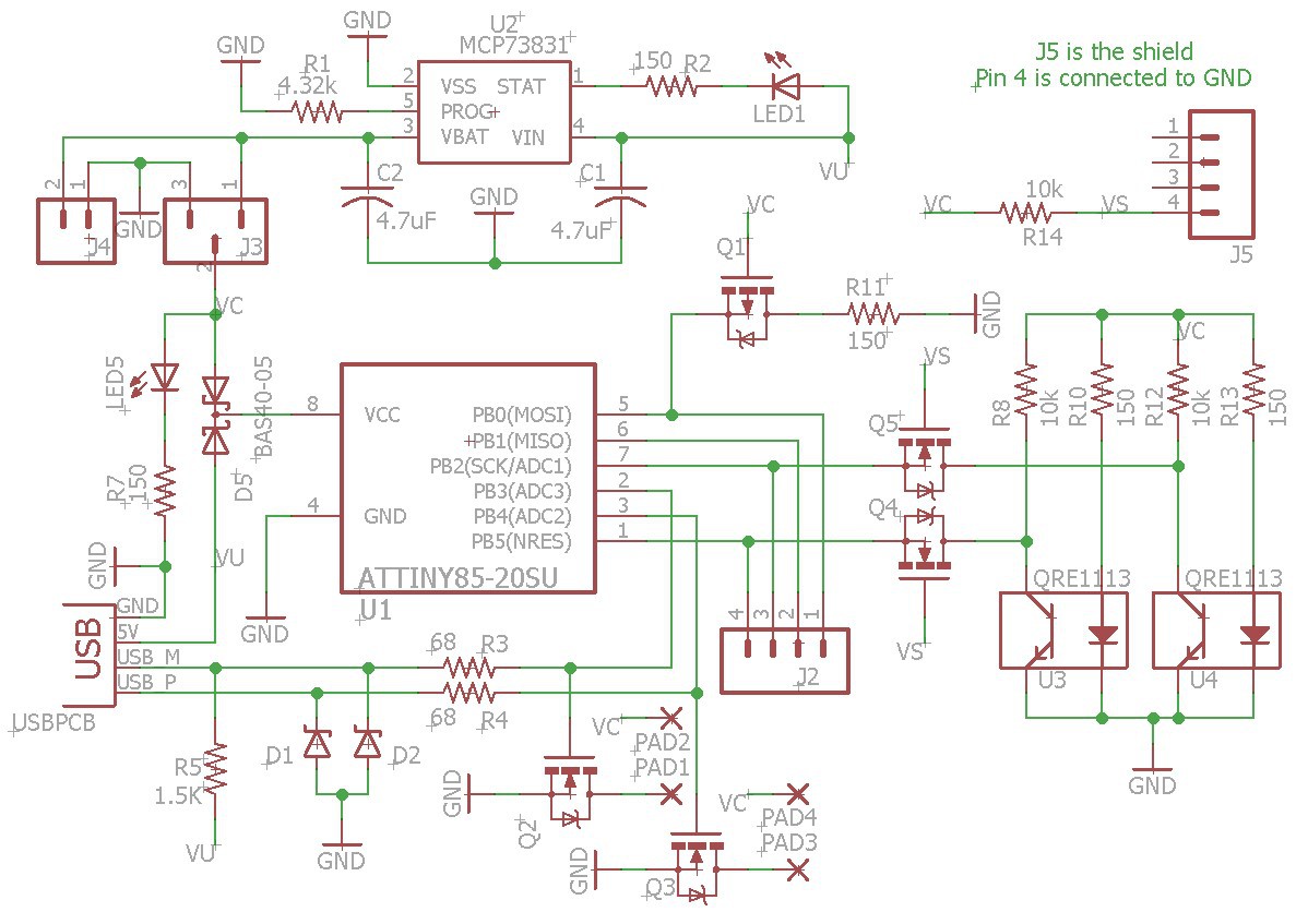
Enhancement Design - Spin 2
In this enhancement design, I replaced the switch with a jumper, fixed and verified both the programming and charging components / circuitry, and added the line following components to the design.
Ignoring the downgrade in motor mounts, I was able to get this design to follow a line pretty well.
Enhancement Design - Spin 3
Incorporating the last part of the design, the shields.
Unfortunately, I ran out of time as school started back up again. I was unable to get this design printed to test. However, once this is completed, the shield design creation and implementation will be easy.
Shield Ideas:
Blue-Tooth: Control your robot from your phone or other blue-tooth enabled device! Just download a simple app to send characters or commands via blue-tooth and configure the robot to listen for these commands.
Obstacle Avoidance: Want both line following and obstacle avoidance? Use this shield to configure your robot to avoid obstacles when the shield is attached.
Solar Cell: Power your robot with solar energy! If your out and about or just can't find a USB port, plug this shield in and charge your robot.
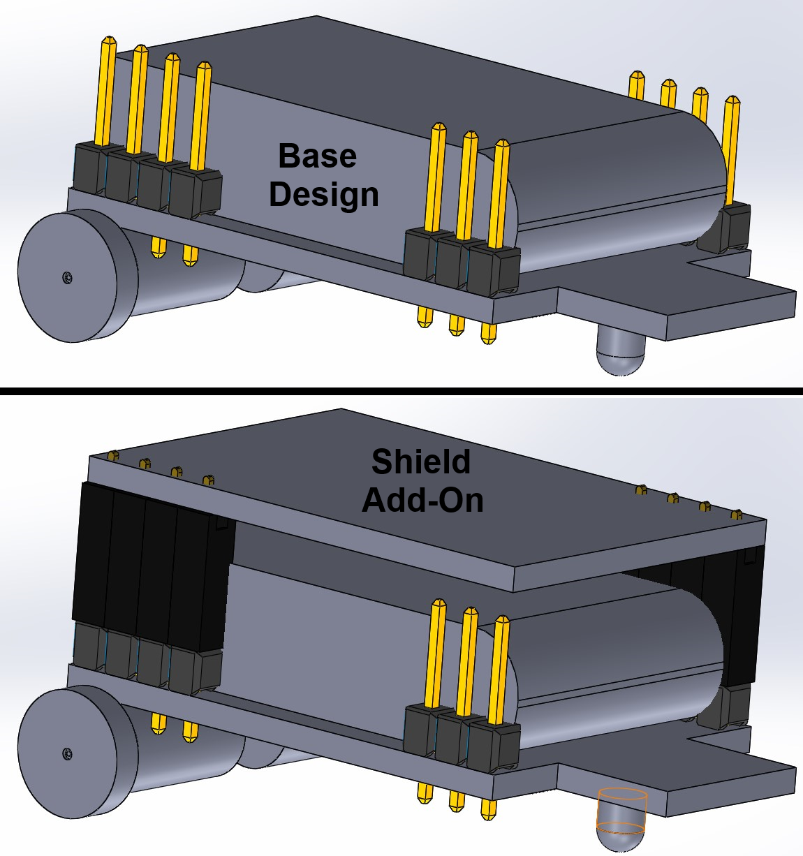
SolidWorks Model
I've made a very rough model of the design in SolidWorks
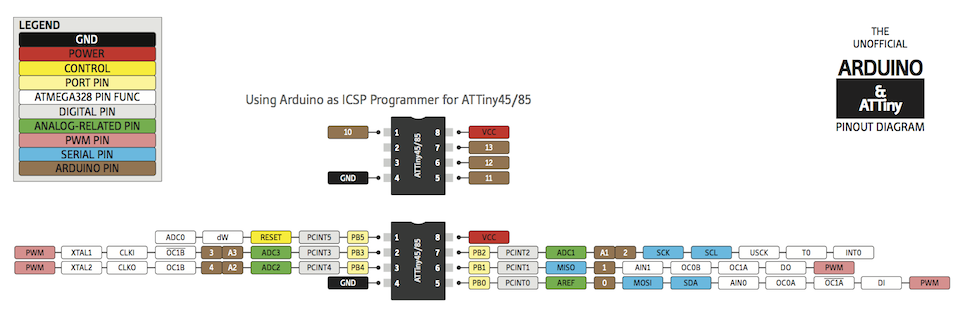
The Micro-Controller
Smaller than a dime, Atmel's Attiny85 is an 8-bit AVR micro-controller with 8KB flash memory, and a 20MHz maximum operating frequency. A specialized bootloader is put onto the Attiny85 to enable PB5 as an additional IO port and to configure the settings required to program it via usb.
Future Possibilities:
Electropermanent Magnets: Imagine a swarm of robots that function independently, but are capable of joining together to complete a task. Each robot would go about doing their own task unless coupled with another robot. When coupled, a predetermined precedence scheme would rule which task was to be followed. Communication would occur through the magnets via PWM signals through the EPMs.
Smaller Design: Using a smaller battery, such as a coin cell battery, the design could be made a little smaller. This was originally considered, but the cost and lifetime of any coin cell battery do not rival that of the small lipo battery.
More Functionality: By incorporating a slightly larger microcontroller, such as the ATtiny84, a single robot could be capable of multiple behaviors without a significant compromise to the size of the robot.

 Ayo Ajayi
 Carl Bugeja
you should use an AP2112K-3.3 for the power regulator! its super simple P1, is VBUS (or VIN), P2 is GND, P3 is EN, connect a 10K-50K resistor to that and VIN, P4 is NC, and P5 is 3.3V! ***NOTE*** that the AP2112K comes is multiple voltage levels, choose the '3.3' variant for 3.3V power and '1.2' for the 1.2V for etc