Close
0%
0%

Moo Bug

Fluffbug, but with a Pi Cow

Similar projects worth following

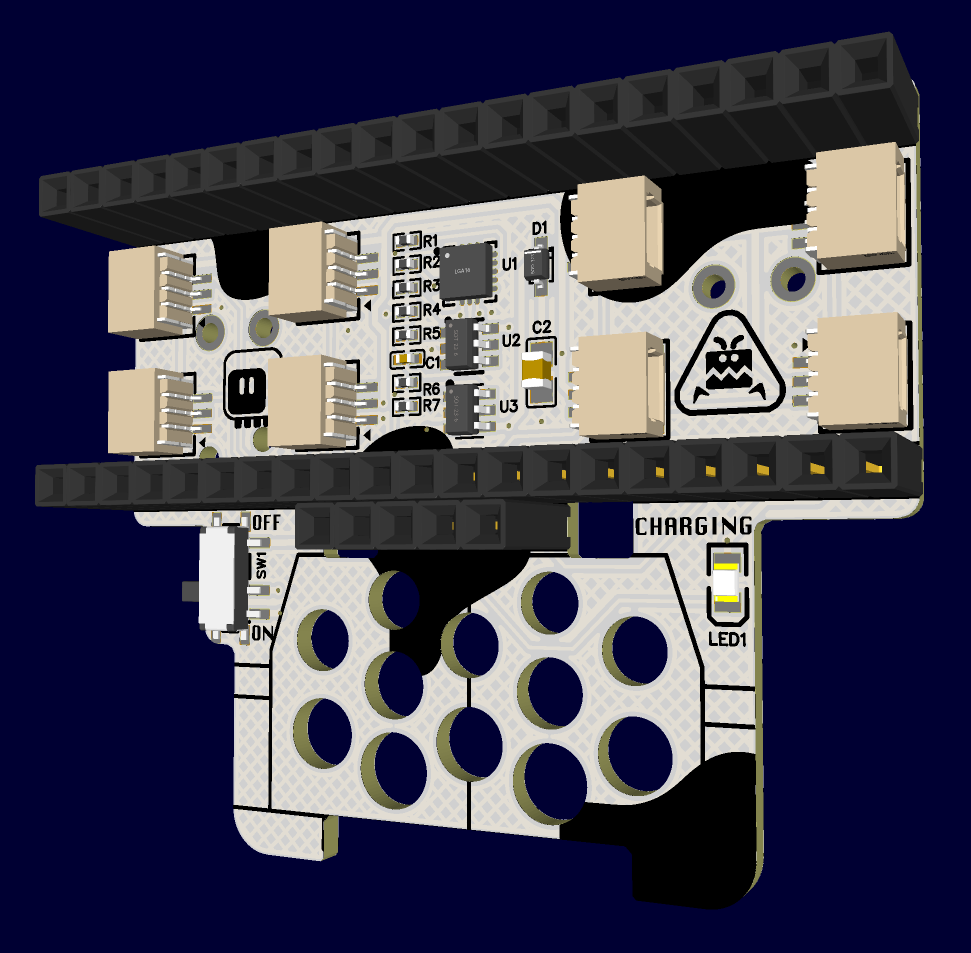
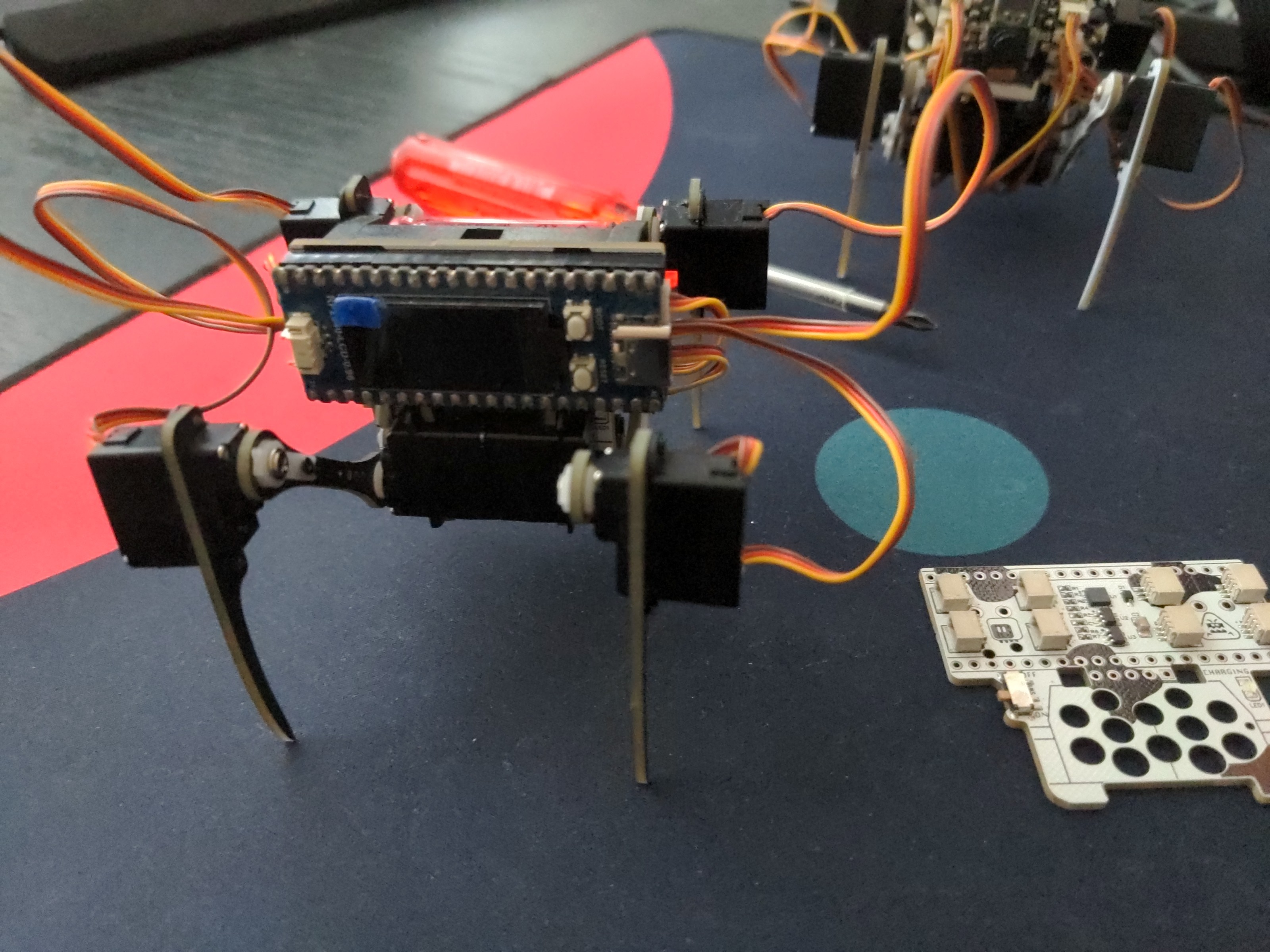
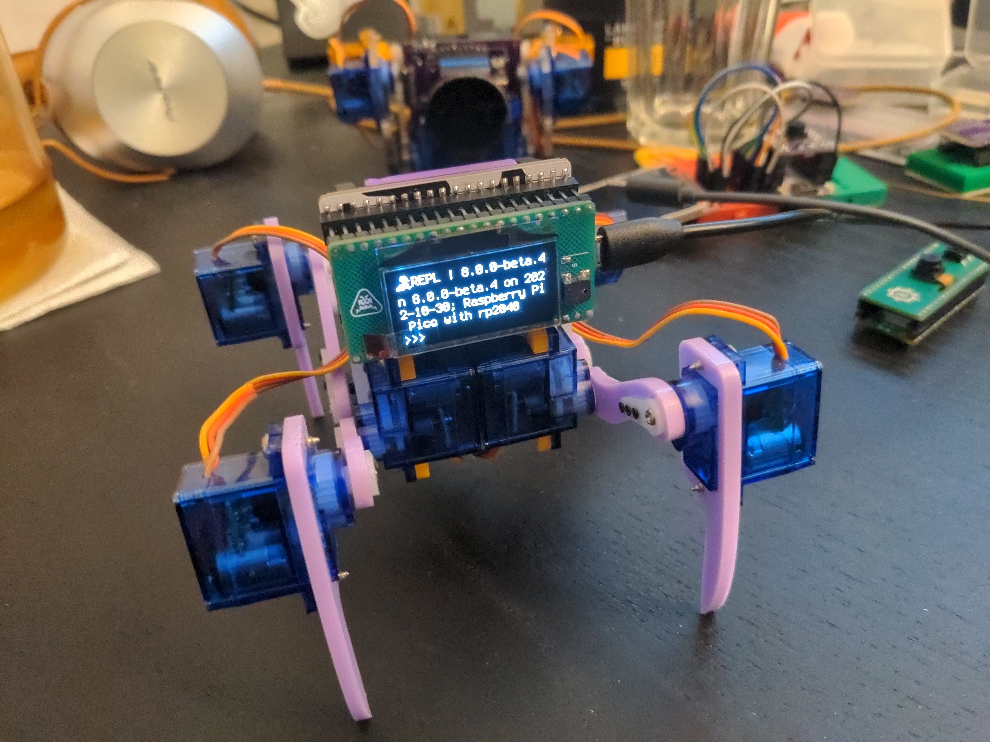
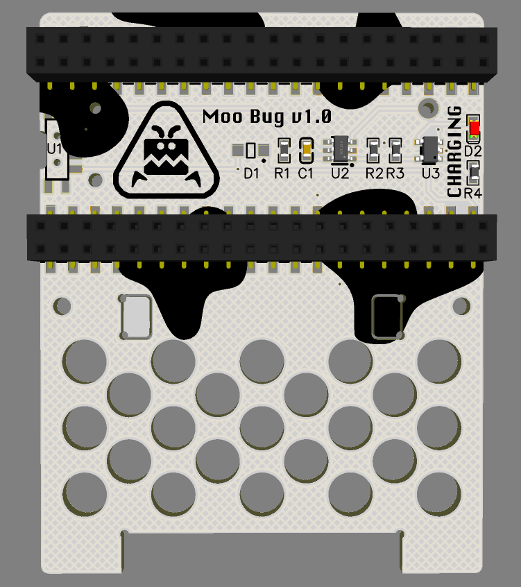
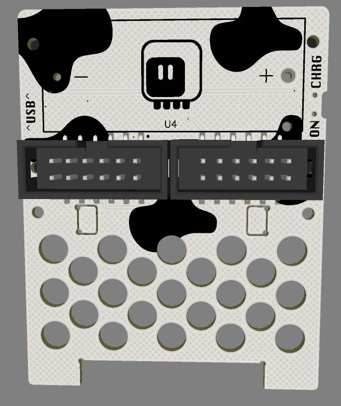
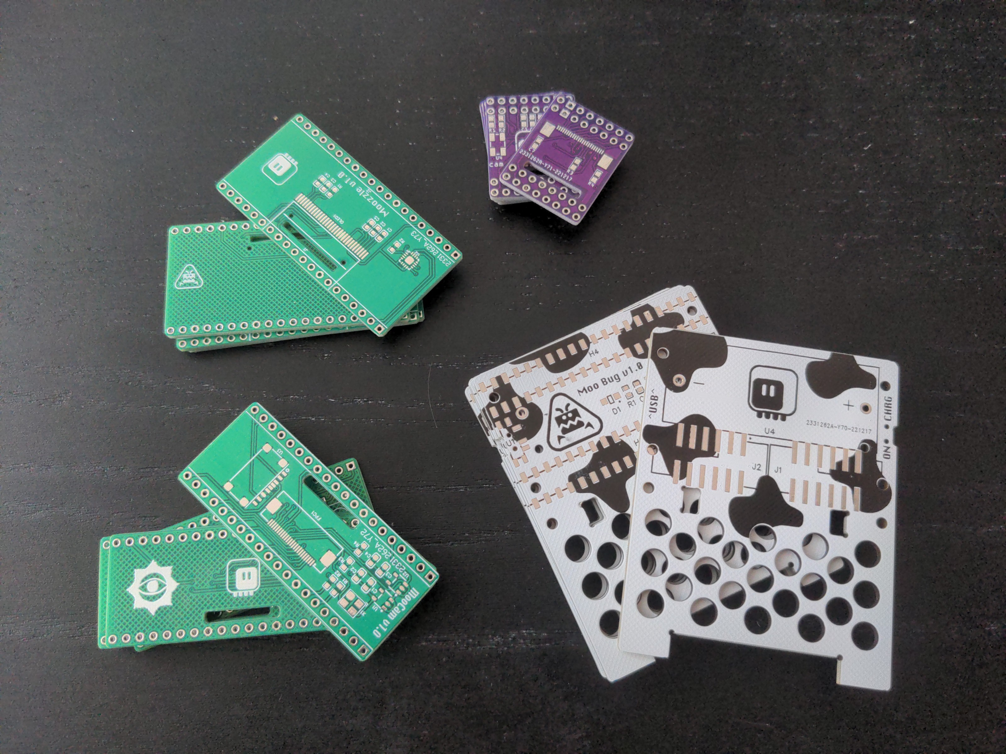
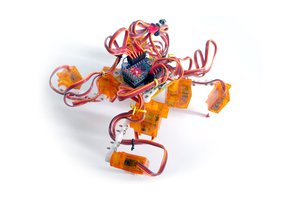
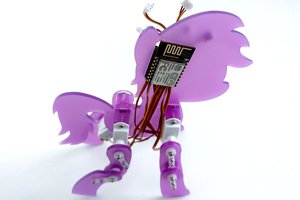
Some time ago I decided that the SAMD21 chip I originally used for the #Fluffbug is not powerful enough, and impossible to get anyways due to chip shortage, and I identified two options I could go with, ESP32-S2 and RP2040. In the end I went with the Lolin S2 Mini board and the ESP32-S2 chip, but I never stopped thinking how would the things go if I went the other way. And then the Raspberry Pi Pico W board was released, adding WiFi to RP2040, and it became even more tempting to try it with the robots. I resisted several months, but eventually caved in, and this is it: Moo Bug, a Fluffbug with a Pi Cow ("pico w", get it?).

  • Going Smaller

    deʃhipu03/18/2024 at 22:26 0 comments

    Smaller robots are easier. Mostly because of the cube law, which says that the weight of a thing grows proportionally to the third power of the size. A robot twice larger is 8 times heavier, and accordingly needs more power to move, bigger batteries, and more robust materials, which are in turn harder to shape. On the other hand a robot that is half the size could be 8 times lighter, needing proportionately less of everything. So if you are a beginner robot builder, you want to start small.

    But not too small! You want to use off-the shelf components, and to be able to work with your hands, preferably without a need of a microscope or special processes. So there is a sweet spot in the size of the robots. When I started with #Fluffbug, that size was mostly dictated by the size of the servos that were available. The 9g cheap blue hobby servos were basically the cheapest and easiest to source actuators for a robot that you could get, and the size of both Fluffbug and Moo Bug that is based on it were mostly based on the size and strength of those servos.

    But situation changes, the popularity of super-small remote controlled models grows, and the sub-micro-servos used in them are becoming widely available. You can now buy 2g servos for only a little bit more than the 9g servos, and since they are later design, they actually have better features. They work with single LiPO voltages, and they often have larger rotation range. They also use much smaller connectors, which lets you save space on the PCB.

    I have been exploring the use of those smaller servos with the #Wee Bug, and I'm pretty happy with what you can do with them and a small board like the Xiao. However, sometimes you want to have more pins, so you can add a display, a speaker, maybe some extra servos for hands, additional sensors and so on. So I decided I need a Wee Bug with the pi pico footprint.

    That's how I came up with the version 3.0 of the Moo Bug. You might be surprised here, if you followed the logs of this project before: I never mentioned anything about the version 2.0! That's true, I had that version designed, the main change was getting rid of the servo connectors and going back to the standard servo plugs. But I never made or published it, so it's lost to history.

    Version 3 switches to through-hole pin headers for the pi pico, to save space, and moves the servo sockets under the microcontroller board. I used a sideways type of sockets this time, so they are pretty low profile. Cable management might be simplified, because you can just tuck the extra cables under the board.

    The electronics is pretty much the same as with the Xiao: battery protection, battery charging, and an accelerometer. The switch and the charging LED have been moved next to the servos, to make room for the servo sockets.

    The servos are connected to the pins on the bottom row, so that pi pico clones with a display or other extra features can be used. The mobility of the legs is slightly limited by the wider top of the body, but that doesn't interfere with walking.

    As with the Wee Bug, the legs are made of PCBs, not laser-cut acrylic – at this size the cost difference is negligible, especially when you need to find very thin acrylic sheet. Of course they could also be cut from MDF or 3D printed, at this weight the material doesn't make much difference. I'm even thinking about a papercraft version of the robot.

  • The OLED Face

    deʃhipu12/30/2022 at 23:09 0 comments

    The PCBs arrived right after the holidays, and I quickly assembled one, moved the whole legs from one of my fluffbugs, and here it is, all working as expected. I just had to update the pin names in my circuitpython code, that's literally it. But then I decided to try and get to work one of the shields – the one with a display and a speaker.

    The display just worked. I used the SH1106 library for displayio, and I just had to rotate the display 180° and add a 2-pixel horizontal shift to adapt it to this particular display. I got really good with that working on all those handheld game consoles.

    The speaker turned out to be a bit more challenging. I used a MAX98357A I2S amplifier, because I had that on a module earlier and I was confident it works well. Well, despite the schematic being practically the same with the module (minus some unnecessary caps, as usual), this one didn't work. The chip is a bit small QFN package, but visually it looked soldered well. I tried a lot of different things, until at fifth re-soldering of the chip with the hot-air gun, it suddenly started working. I suppose looking good is not enough. Of course with such a tiny speaker the quality is questionable, but it does sound properly robotic, and it's surprisingly loud (I hardwired the amplifier to maximum gain).

  • The PCB Design

    deʃhipu12/30/2022 at 22:53 1 comment

    This is my first project where I completely switched to EasyEDA as a PCB design tool. I honestly tried KiCAD several times over the years, and it's just so hilariously bad at exploring designs, that I gave up on it. EasyEDA is still far from ideal (especially the copper fills), but it's not completely unusable.

    In any case, I followed up on my fluffbug work, of course, but I made everything except for the battery holder surface-mount. I found some pretty nice low-profile smd female headers on LCSC, and the IDC connectors for the servos also exist in SMD versions. This actually gives me much more room on the PCB, because headers no longer take up both sides.

    There are still a few pilot holes for all the components, so there was some work squeezing it all to fit, but in the end it came out rather compact. Since the headers are double-row, I can use them to add bigger "face" shields for the robot, with things like displays, cameras, sensors or speakers. In fact, I went ahead and designed two shields, one the size of the pico with a camera, and one bigger, with an oled display and a speaker.

View all 3 project logs

Enjoy this project?

Share

Discussions

Similar Projects

Does this project spark your interest?

Become a member to follow this project and never miss any updates