 deʃhipu
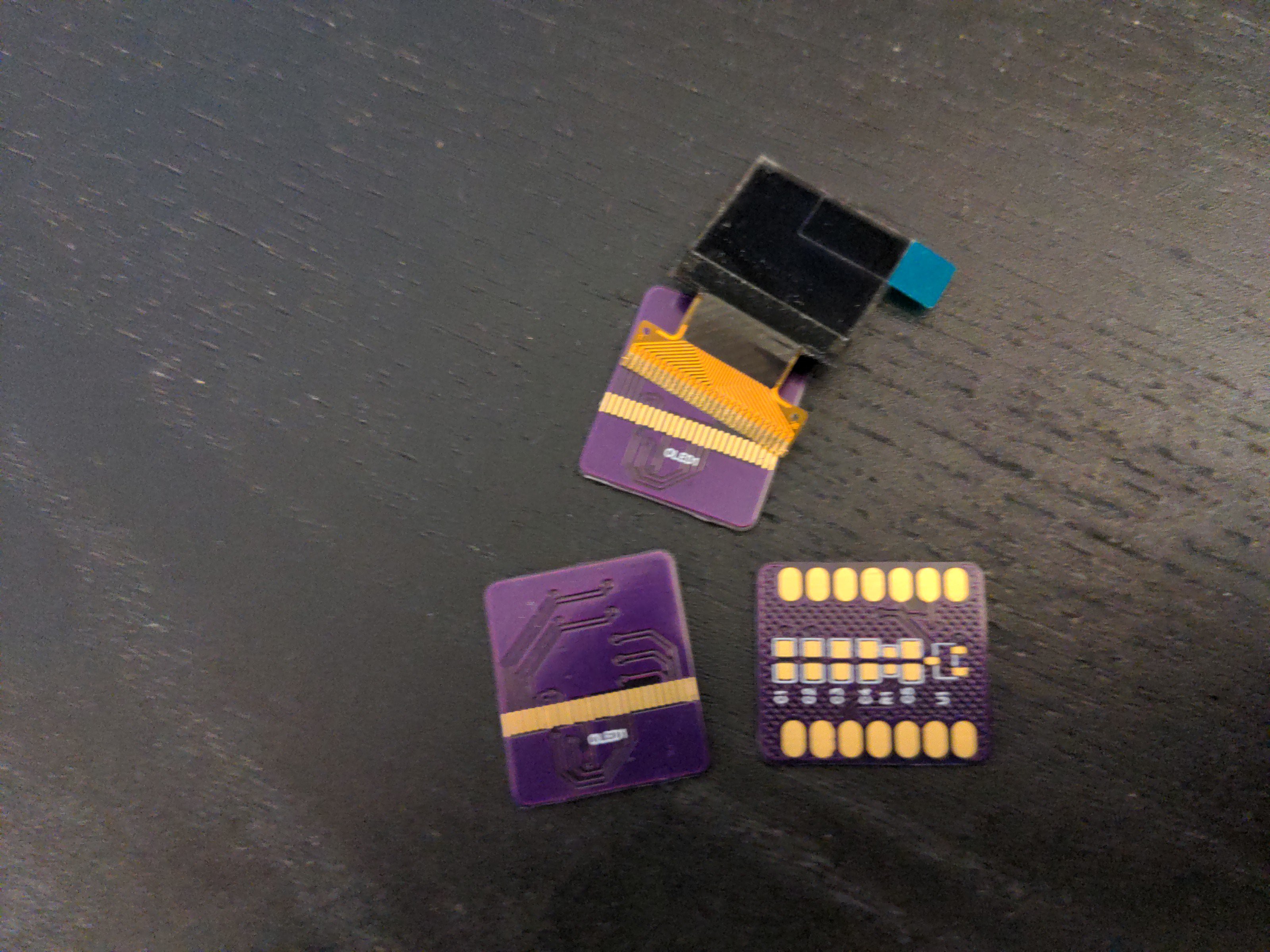
A while ago I made a display shield (mask?) for the Wee Bug, but because it needs additional pins to talk to the microcontroller, it only works with the Waveshare Mini boards, and not the Xiao or QtPy boards, that don't have those extra pins. But then I found this tiny 0.66" OLED screen in my drawer, and thought "wait a minute, this display can use I2C for communication, and I already have an I2C bus for the accelerometer on the robot, so it would need no extra pins". All I need is a breakout board for it. Oh, and the tiny little issue of the reset circuit.
What reset circuit, you ask? Well, I happen to know from experience, that those display will not work correctly when you just switch them on and start sending them data. They need to be restarted, physically, with the RST pin, a short moment after being powered on. I'm not entirely sure why, and why this isn't built into the chip's initialization, but that's how it is. If you don't do that restart, they will just keep displaying random pixels, ignoring any update commands.
Normally I solve this in software. I have a GPIO pin connected to RST, and I wiggle it as a part of the display initialization. Easy enough. But in this case I don't have an extra pin to spare. So I need something else to wiggle the pin for me. A reset circuit.
As always, as the first thing I went to Adafruit's excellent documentation, and looked at the schematics of their own display modules using similar displays. Sure enough, they had their reset circuits on them, in the form of an APX803L40 chip. Neat, just a single chip doing what I wanted, and I was afraid I would have to muck about with transistors and capacitors and resistors and diodes and who knows what else. The only problem is that the schematic didn't specify what threshold voltage should the chip have, so I ordered the 3.3V (because that's the voltage I will use to power the display) and 2.5V (because that's the 2/3 of the final voltage) versions. Then I quickly made a PCB and since it was so small, ordered it from OSHPark.
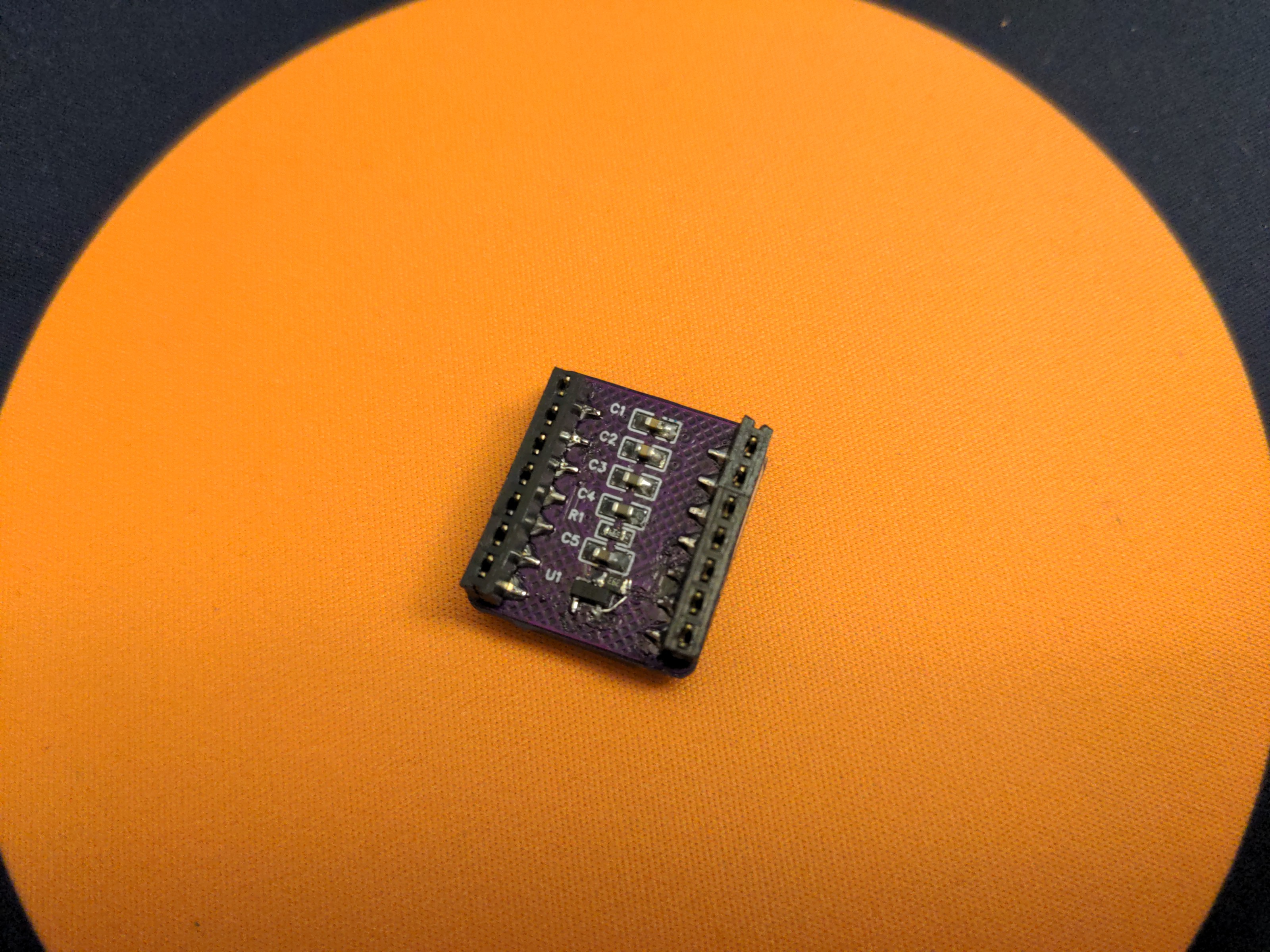
When it arrived a few weeks later (free shipping from US is slooooow), I quickly soldered it up and tested. I immediately realized that I forgot to add the pull-up resistors on the I2C bus, but that's fine since the robot already has them, for the accelerometer. But even with those, it didn't show up on the I2C bus scans. What's wrong?
At the time I was quite sick, and I didn't have the energy for too much experimenting. I just verified that it still didn't show up when I replaced the reset chip with a pull-up resistor, but didn't pursue it further. It went into a drawer.
This week I felt better, and I decided to give it another look. I went over the schematic and compared it with examples of modules I found online. One difference between my schematic and the Adafruit one is that I didn't break out the RST pin, and I didn't include the pull-up resistor they have on it. A quick bodge job to add that resistor didn't help. Hmm. Another difference is that I didn't ground the unused pins. But the datasheet didn't say they have to be grounded... I tried another bodge to ground all those pins, and still nothing.
What else could be wrong? I still suspected the reset circuit, so I desoldered the reset chip, and put a pull-up resistor in its place. And suddenly it showed up on the I2C scan! Turns out I need both the CE pin pulled low, and the RST pulled high. Of course the display wouldn't work like that, since it didn't get its reset after power up. So I once more put the reset chip in there, *and* added the pull-up resistor, while *at the same time* having CE connected to GND. That was it, that made it all work.
It certainly took me more time than it should, but I have an animated eye working on the robot now.
Discussions
Become a Hackaday.io Member
Create an account to leave a comment. Already have an account? Log In.