 enrique
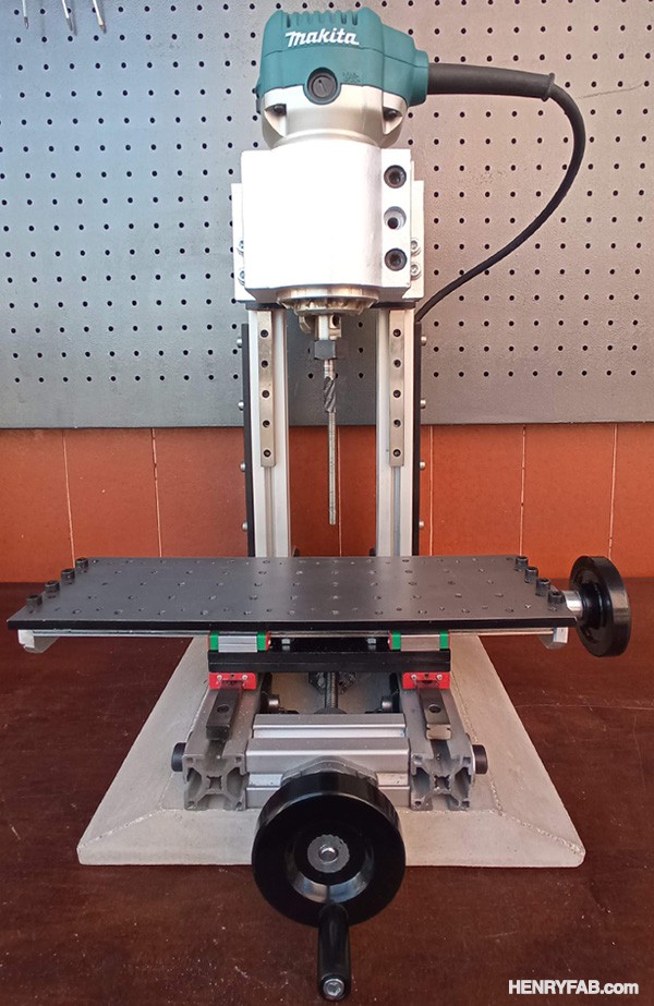
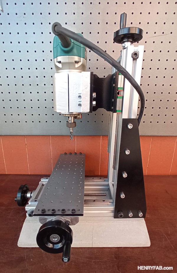
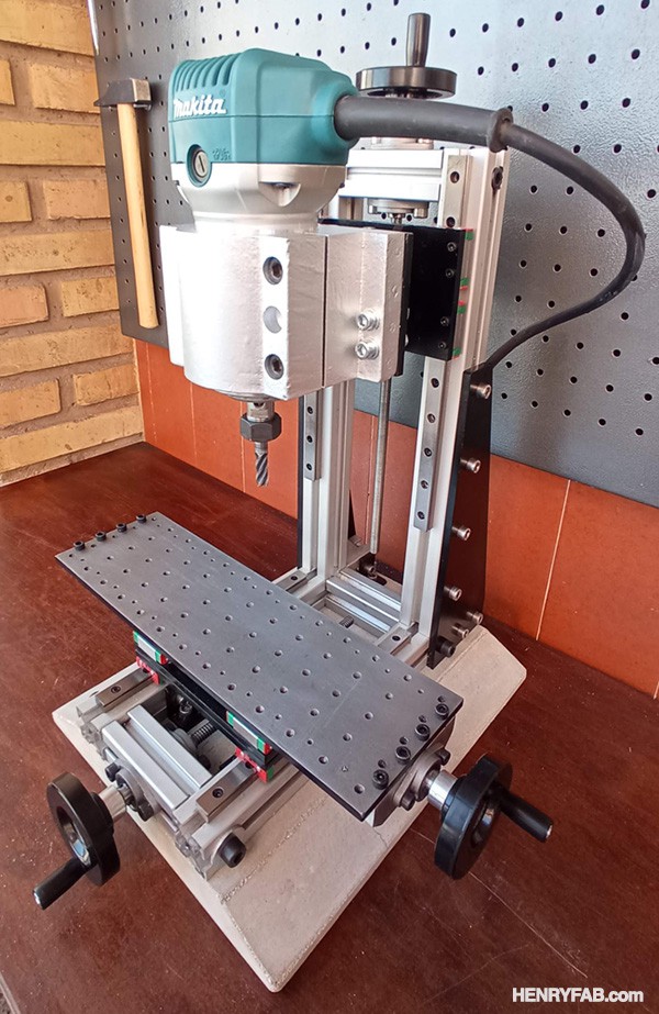
I would like to be able to machine small mild steel and aluminum parts at home for my projects. A commercial milling machine costs at least about 1000 usd / eur and even the smallest models are too big for my small home workshop. This router is slightly larger than a proxxon, smaller than a commercial type bf16 router, and costs about half (maybe a little less if you can recycle or reuse materials).
- 2x 300 mm T-Slot 3030 aluminium (buy here)
- 2x 300 mm T-Slot 3030 aluminium profile
- 3x 80 mm T-Slot 3030 aluminium profile
- 2x MGN12 200mm linear guides (buy here)
- 2x MGN12 250mm linear guides
- 2x MGN12 300mm linear guides
- 6x MGN12C Skates (buy here)
- 1x 250mm 8mm Pitch-Lead 1mm Trapezoidal Screw (buy here)
- 1x 300mm 8mm Pitch-Lead 2mm Trapezoidal Screw
- 1x 300mm 8mm Pitch-Lead 2mm Trapezoidal Screw
- 1x Trapezoidal brass nut 8mm Pitch-Lead 1mm
- 2x Trapezoidal brass nut 8mm Pitch-Lead 1mm
- 6x Bearings with bracket KFL08 (buy here)
- 3x 63mm Cranks with rotary knob and 8 mm shaft (buy here)
- 4x M6 mortise threads (buy here)
- 1x 6mm thick steel sheet or steel parts cut by laser cutting company
- 1x holder for 65mm diameter milling machine (buy here)
- 1x 65mm router like Makita RT0700C (buy here)
- Allen din912 screws M3, M5, M6 and M8 (buy here)
- Cement and sand (preferably buy in a nearby DIY store)
- Detailed plans (download here)
Step 1: PREPARATION OF CONCRETE BASE
YOUTUBE VIDEO:
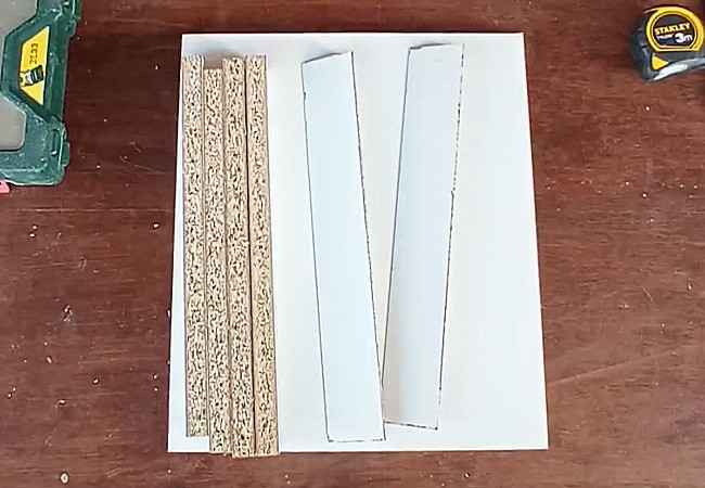
Using a white melamine chipboard mold, easy to find in any DIY or board store, we fabricate a 260 x 300 x 30mm (W x D x H) cavity. Optionally and just for aesthetics we can add some squares in the mold to obtain the final piece with a chamfer as shown in the piece that I have made.
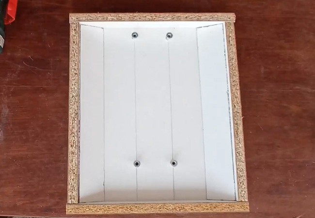
The mold is vertically inverted, so that the lower zone of the mold will contain the upper zone of the final piece. To have 4 anchor points in the final piece, we must fasten 4 metric 6 threads at the bottom of the mold, so that they will be covered with cement. We will see these threads appear in the upper area of the final piece. See position of the threads in Plane 4 of the drawings .pdf.
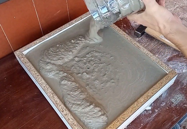
We mix 80% gray cement, 20% coated sand and a few grams of fiberglass in strips to reinforce the piece. Later we are pouring water to the mixture at the same time that we stir until we have a homogeneous paste.
Theoretically, the volume of the piece is 2.34 liters, but from my experience with concrete molds and because of how cheap the material is, I recommend doing more than twice the mix of cement and sand.
We pour the mixture on the mold and we are hitting from the lower area to try to remove all the air bubbles and settle the mixture. It is important that the mixture reaches the upper area and try to make a single pour. If we make two mixes or different pours, we will have a better chance of obtaining a piece with cracks or fragile.
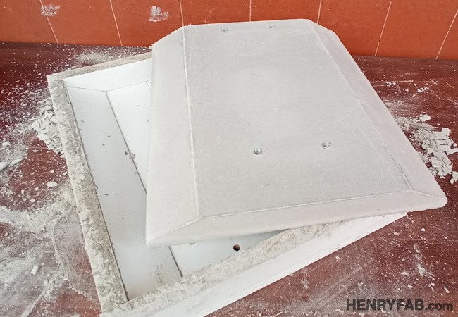
We wait at least 7 days before unmolding. It's really tempting to do it before, I know. Once removed from the mold, we sand the edges and small imperfections. The part can be sealed to avoid grease or paint stains. In my case I have used Barpimo's stone and concrete sealer.
Step 2: CUTTING AND MACHINING OF ALUMINUM PROFILING
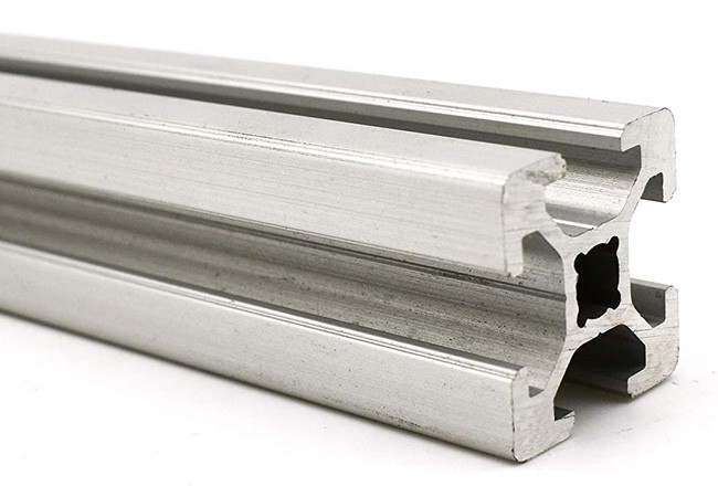
We are only going to use one type of aluminum profile, in my case it has been a 30 × 30 mm Bosch Rexroth brand profile, but you can use a similar profile from any manufacturer.
In total we will need 1540 linear mm (a little more than a meter and a half) divided into the following pieces:
• 350 mm (2 units)
• 300 mm (2 units)
• 80 mm (3 units)
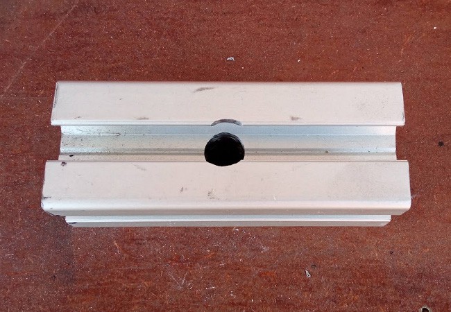
350 mm pieces: We will need to make 1 8 mm hole in each piece (see Drawing 3 of the downloadable PDF). On the other side and starting from the hole closest to the end, we will mount the 250 mm linear guide with a 2.5 mm hole and M3 thread.
300 mm pieces: We will need to make 2 8 mm holes in each piece (see Drawing 3 of the downloadable PDF). On the other side and starting from the hole closest to the end, we will mount the 200 mm linear guide with a 2.5 mm hole and M3 thread.
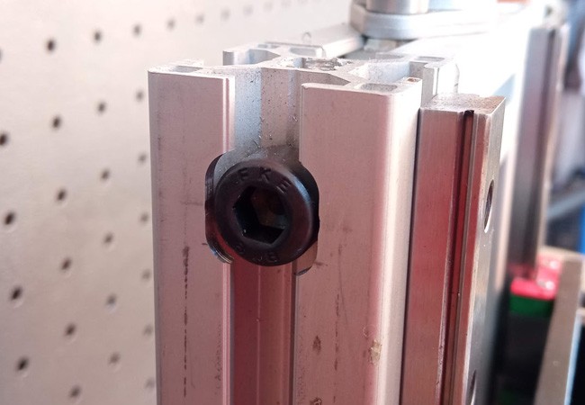
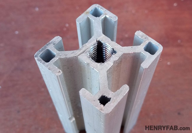
80 mm pieces: In the three pieces we will make an M8 thread on the tips, depending on the profile model, this thread could be a couple of mm lower. In addition, in two of the pieces we will make a 10 mm hole in one of the faces (see Drawing 3 of the downloadable PDF).
Step 3: CUTTING AND MACHINING STEEL SHEET
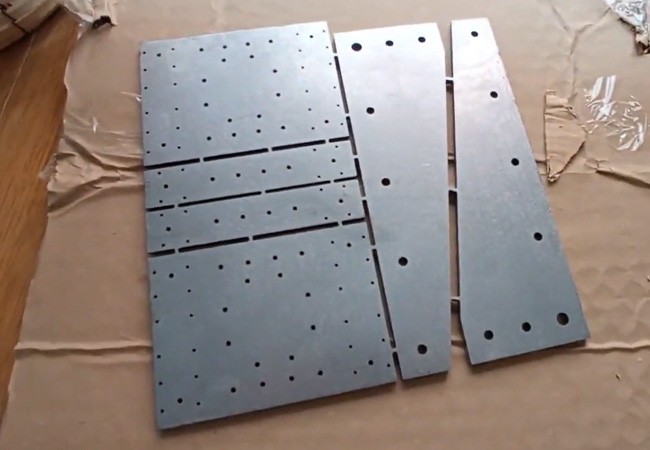
An important part of the machine is based on pieces of 6 mm thick steel sheet (see drawings from 6 to 17 of the downloadable PDF with all the measurements of the pieces), we have two options to obtain these pieces:
• ECO option: Print template (file attached for this purpose), stick them to a 6 mm steel flat. Drill all the holes and cut all the parts with a radial grinder.
• PRO option: Make use of the .dxf files (I attach files in separate pieces and in a single set) to send them to a laser cutting company, receive the perfectly cut and drilled pieces.
The .dxf files to send to laser cutting have the holes where you have to make smaller threads than usual to avoid loose threads, so you simply have to go over with the drill prior to threading and then make the tapping with the taps.
In my case I have used normal carbon steel (without special properties) but stainless steel can be used.
Step 4: ASSEMBLY AND ADJUSTMENT
Ç
YOUTUBE VIDEO:
Download PLANS HERE !
Structure
* We screw the linear guides onto the 300 and 350 mm long aluminum profiles, without tightening.
* We assemble the structure of aluminum profiles as shown in Fig. X, Some joints are made with an Allen screw M8x50 and other joints are made, we have not tightened the joints yet.
* We mount the square-shaped sheet on the aluminum profiles.
* We assemble the profile structure on the concrete base with metal brackets.
* We mount bearings with support, two for the Y axis and another two for the Z axis.
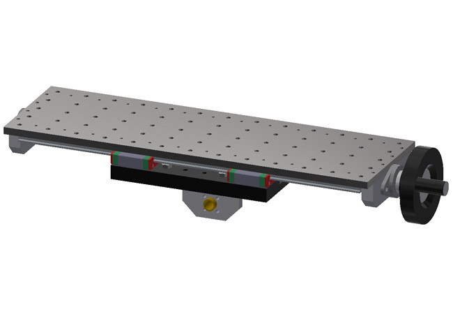
XY axis
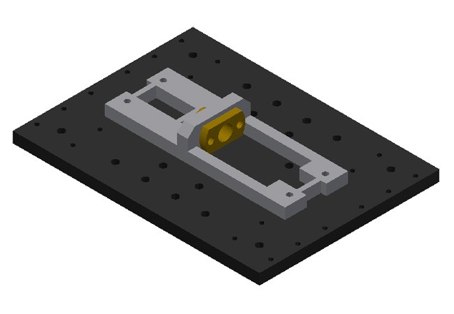
* We mount the brass nut for a 2 mm pitch on one of the «YZ nut bracket».
* We mount the 2 mm pitch brass nut on «Nut support X», it is possible that this piece will have to be filed through 2 of the 4 non-consecutive holes, due to the lack of space where it will be housed.
* On the piece «XY Axis Plate» we mount «Nut support YZ» and «Nut support X».
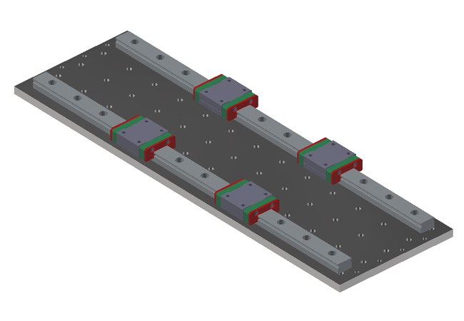
* We pass 4 skids through the 200 mm guides (Y axis), previously assembled in the «Structure» section.
* We assemble the previous assembly on the Y axis skates. * We mount the two 300 mm guides on «Top plate».
* We pass 4 skates through the 300 mm guides.
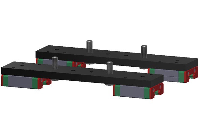
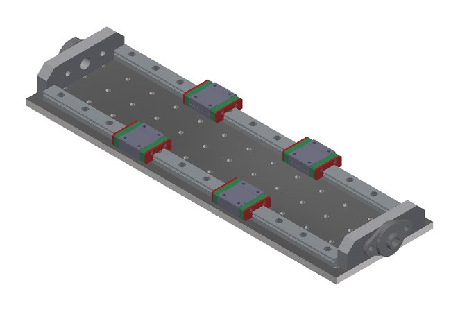
* We mount the two plates "X Axis Spindle Support" at the ends «Upper plate».
* We mount a bearing with support at each end of the previous set.
* On the piece «Elevador Skates», we leave two M5 x 15 mm hexagonal head screws in one direction, and in the opposite direction (that of the countersunk) we screw the plates to the runners in the 300 mm guides.
* We join the two sets «XY Axis Plate» and «Upper Plate» by means of the hexagonal head screws that we have just passed. Important to keep square before tightening.
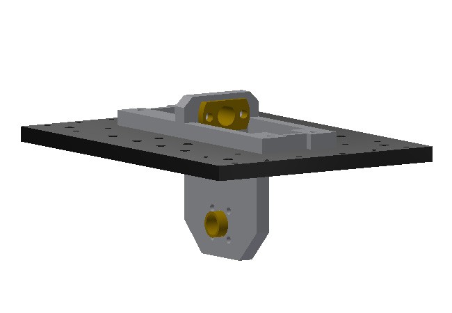
Z axis
* We pass the 4 remaining skates through the Z axis guides.
* We mount the 1 mm pitch brass nut on the remaining set «Nut support YZ».
* We assemble the «Z Axis Support» structure of 4 welded plates on the skids.
* We mount «YZ nut support» on the previous structure.
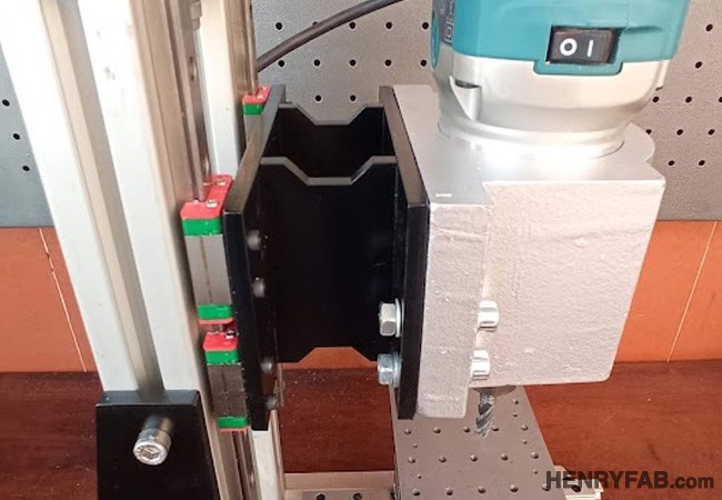
* We mount the 65 mm diameter milling machine support on the previous structure.
* We mount the milling machine on the support and tighten.
Last settings
* We pass the 2 mm pitch spindles on the X and Y axes. We tighten the studs of the bearings.
* We pass the 1 mm pitch spindle on the Z axis. We tighten the studs of the bearings.
* We mount a crank on each of the axles, ideally they should protrude approximately 27 mm from the bearing.
* With precision squares and preferably with a dial gauge, we correct the squares and tighten all the hardware of the structure to have a perfectly adjusted machine.
Download PLANS HERE !
And finished!
I hope I have made the instructions as clear as possible. If there is any doubt or you detect an error, please comment it and I will try to solve it as quickly as possible. Thanks for getting to this point!
Download PLANS HERE !
After finish building, I tested some bits with little aluminium block ¿would you like to see?
YOUTUBE VIDEO:
¡Thanks a lot for watching!