 Patrick Chwalek
Note: I am waiting to publish an academic paper on my work here, so I am not going too in-depth into the sensing subsystems or what I am trying to sense. However, I thought this log was interesting, so I decided to post this anyways.
One of the most expensive pieces of this project is the flexible circuit board I have going through the frames. In the previous iteration of this project, Project Captivate, you can see the aforementioned flexible circuit board in the how-to section. This circuit board is designed to serve as a signal pathway between the two rigid circuit boards I have located in both arms of the glasses and to house some of the sensing subsystems and all the LEDs. In Project Captivate, as outlined in our paper, we designed the boards to be robust, which meant that our design had to consider dynamic bends (i.e., reoccuring bending of the flexible boards). The flexible printed circuit (FPC) was designed to go through the hinge of the glasses, so those locations were designed to be only 2-layers to limit stresses, including shear stresses. For the remainder of the board, where only static bending (i.e., one-time bends) exists, we designed it to be 4-layers to give us the most flexibility in routing.
In AirSpec, I kept the original form factor of the Project Captivate board but upgraded the analog non-contact temperature sensors to digital calibrated equivalents. However, I had one additional constraint with AirSpecs: I wanted to keep this FPC board the same if iterating on this system in the future. In short, I did not want to pay the fixed setup cost of a few thousand to make these boards since I only needed 5-10 at a time. Instead, I wanted to design this new FPC board with extensibility in mind so that the FPC has all the foundational circuit and pathways needed but allows for additional boards to be connected to it in the future with various sensing subsystems.
knew the main place we would want to put new additional sensors is in and around the nose area, so that is where I wanted to make the FPC board extensible. Now this is where I leveraged some of my experience with Project Captivate, where we used varied layers in an FPC board depending on physical and electrical constraints. My goal here was to design a secondary FPC board that would be soldered onto the original board that would include the sensor payload. The primary FPC board will have all the power and signal pathways to allow for a wide variety of sensor subsystems to be attached, both outward and inward (i.e., user-facing) facing.
At around this time, PCBWAY reached out to me to collaborate, which I gracefully accepted since, even today, flexible circuit boards are expensive to manufacture at layer counts higher than 2. PCBWAY offered to help me manufacture a 4-layer daughter board, allowing me to experiment with this idea.
Modifying the Original FPC
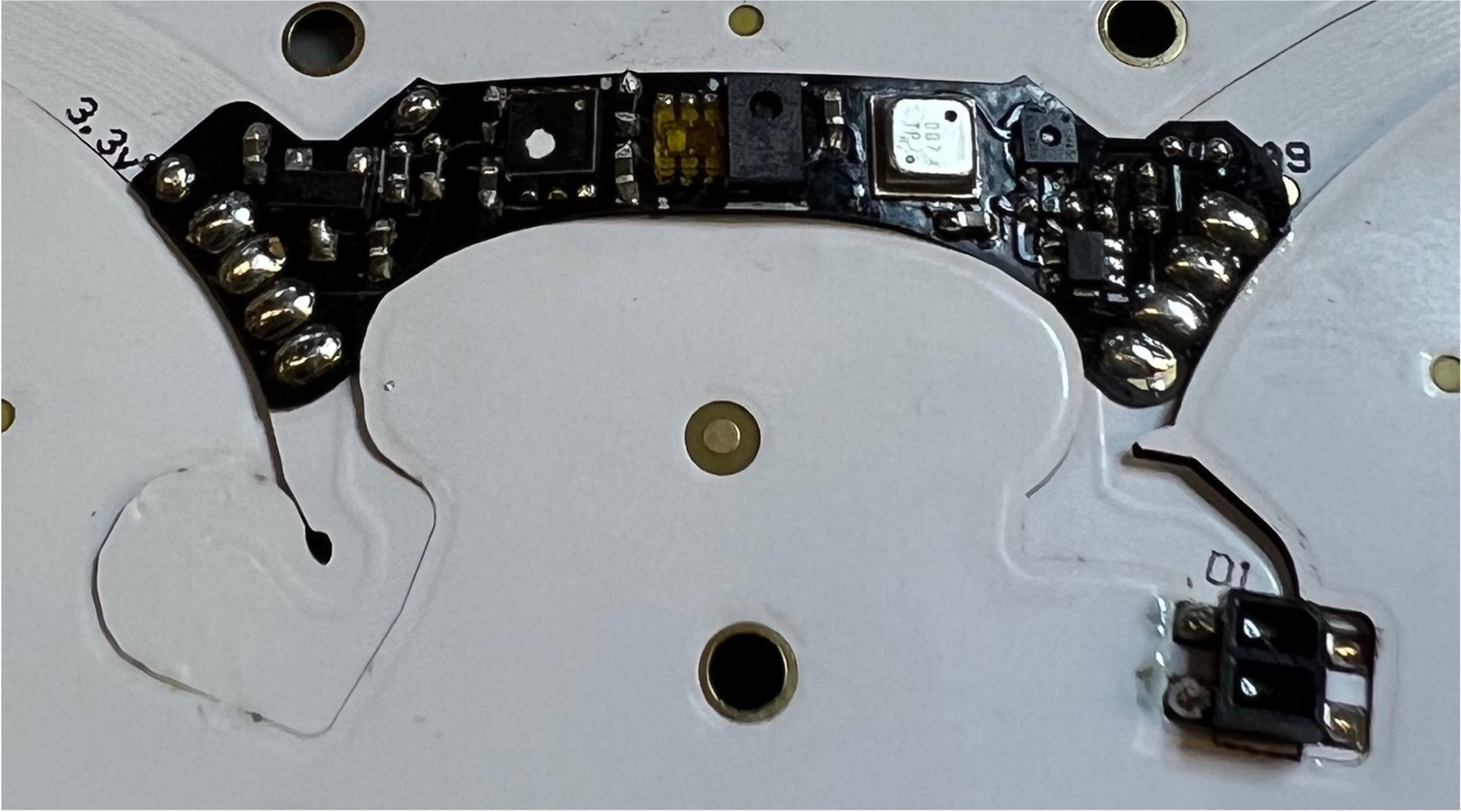
The original FPC was modified to allow a daughterboard to be soldered onto it. The constraint was having the same board be soldered onto it from the front or back. To do this, I remapped 8 through-hole pads existing on the board to both available I2C busses, ground, and the unregulated voltage from the batteries (i.e., 3.7V). I chose to use the unregulated voltage since, depending on the power constraints of the daughter board's sensor subsystem, I didn't want to overload my 3.3V bus. I figured that whatever subsystem I design in the future, I could put a regulator on there to drop it down to the voltage I need (e.g., 3.3V, 1.8V, etc).


Testing out the Rigid Daughterboard
After designing the daughter board, I manufactured a rigid version of the board to ensure the circuit was functional. As you can see in figure 3, the board was soldered onto the primary FPC board (I apologize for the flux residue and shotty soldering, but I was a bit rushed). After soldering, I connected the primary board to the remainder of my system, wrote test firmware, and everything appeared to work.

Testing out the Flexible Daughterboard
Knowing that my daughterboard circuit is functional, I contacted PCBWAY to place the order for my 4-layer flexible board. Given the cost of assembly, I opted to assemble it myself since this was a test run anyways. After receiving the boards, I populated one with all the sensors, regulators, and passives. Then, I attached the daughterboard board to my primary FPC board and performed a full functional test. Everything appeared to work just fine without any issues.
The Bend
So here is where I get to brush off that mechanical engineering degree. From my experience with flex circuit boards, I know how fragile all the traces and pads are. That fragility becomes a problem when you subject the board to stresses (e.g., during bending). So, when you're soldering an additional board to the flexible circuit board at multiple points and attempting to bend both boards together, you will experience shear stresses in the solder joints. This could lead to breaking the circuit during assembly or potentially fatigue issues down the road.
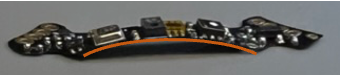
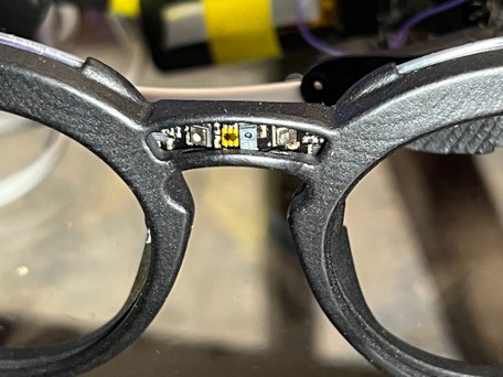
To circumvent the issue, I prebent both boards to the desired profile (Figure 7) and soldered them together. The final result is shown in Figure 8.
Thanks
Thank you PCBWAY for sponsoring the flexible daughterboard fab. As a student interested in hardware design, getting discounts and sponsorships from manufacturers and suppliers is key for iterative experimentation and pushing the bounds of what is possible. I have been using PCBWAY for the last few years now, purchasing a variety of rigid and flexible PCBs and a few PCBAs. I have always been satisfied with their quick turn time and affordability, and I couldn't recommend them more.
Discussions
Become a Hackaday.io Member
Create an account to leave a comment. Already have an account? Log In.