 lion mclionhead
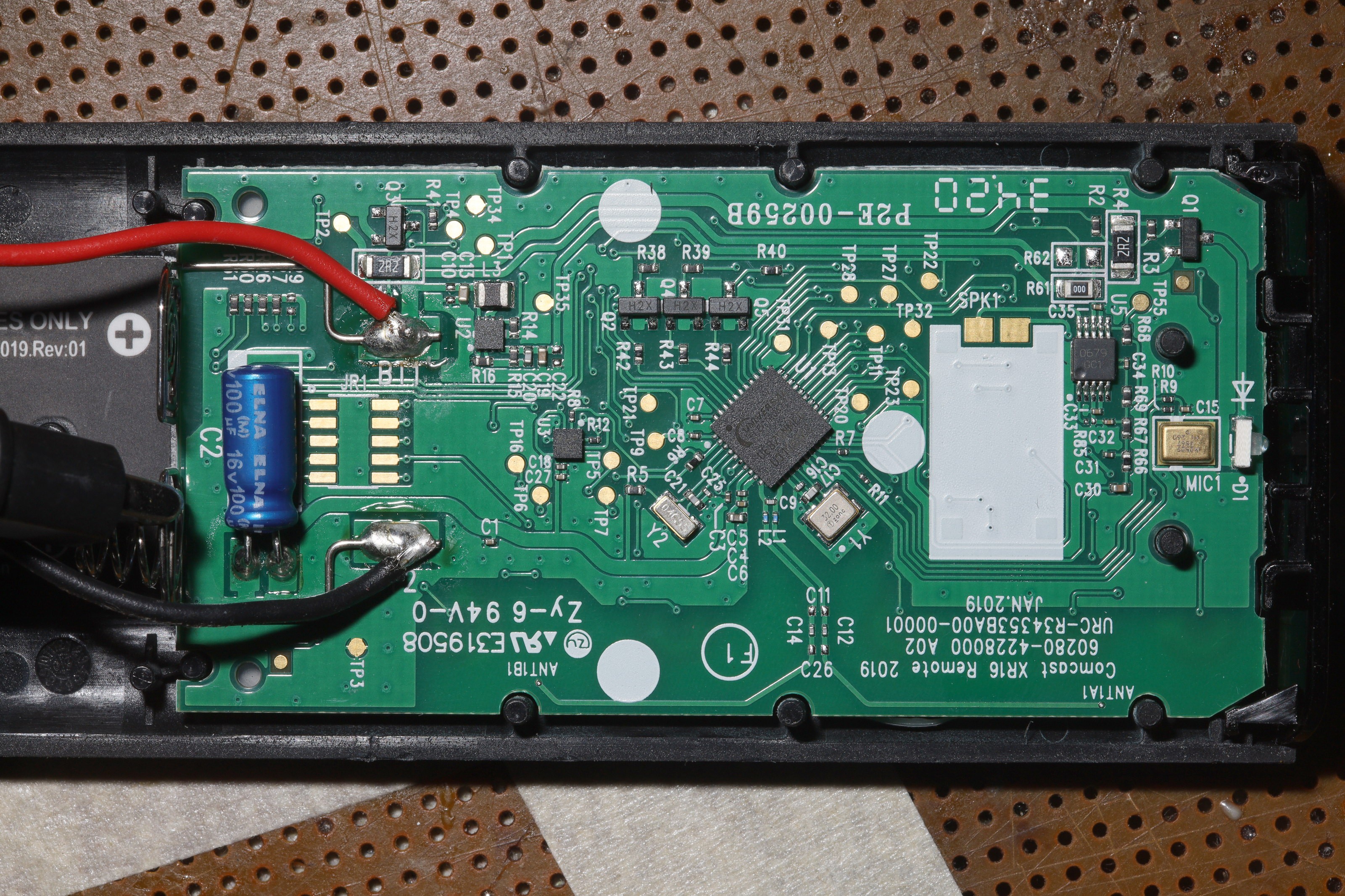
TP1 - battery +
TP2 - battery +
TP3 - GND
TP4 - battery +
TP16 - momentary battery +
TP20 - pulse GND if back, left, TV input, *
TP21 - pulse GND if MIC, select, -, power
TP22 - pulse GND if home, right, +, i
TP23 - pulse GND if down, up, mute
TP27 - battery+/pulse GND if up, *, i, -
TP28 - battery+/pulse GND if back, MIC, home
TP31 - battery+/pulse GND if left, right, select, down
TP32 - battery+/pulse GND if TV input, power, +, mute
TP35 - 3.3V This turns on as soon as a button is pressed but stays on for several seconds after the button is released.
TP20, 21, 22, 23 are always battery+
TP27, 28, 31, 32 are battery+ & pulse GND only when their group is pressed
GND pulses are 30us long, repeating every 25ms
Power & MIC suck 40mA. The rest suck 20 - 30mA. The existing brain can stay around just to manage power & backlighting. It blinks error codes & sucks amps but back lighting looks better than nothing.
Q1 is a P transistor which feeds the LED battery +.
Q5 lights a blue LED when the mic button is pressed.
Q4 lights a green LED when any other button is pressed.
Q2 flashes a red LED to signify an error after every button press. That could be disconnected.
11 signals in total would be required. The buttons require 8 signals. Then there's 3.3V, GND, & LED.
There's room for a 27x24x5mm board. A bunch of standoffs press the board against the buttons. Former space for the speaker can be used for excess wire.
Discussions
Become a Hackaday.io Member
Create an account to leave a comment. Already have an account? Log In.